

Floating Board-to-Board Connectors: How Self-Aligning BTB Technology Solves Alignment Challenges in Dense PCB Assemblies
As electronic devices shrink and PCB densities increase, the tolerance stack-up problem in multi-board assemblies has become one of the most persistent manufacturing headaches for design engineers. Misalignment between parallel PCBs — caused by component placement tolerances, solder joint height variation, and mechanical enclosure fit — can produce stress on connector pins, intermittent open circuits, or outright assembly failure. The floating board-to-board (BTB) connector is the engineering solution to this problem.
What Is a Floating BTB Connector?
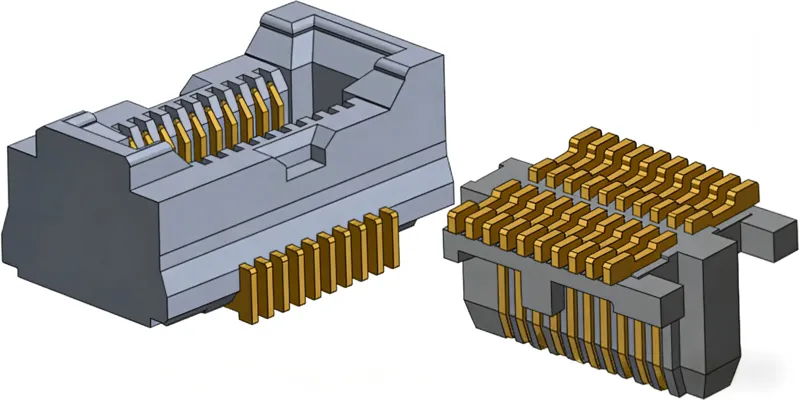
A floating BTB connector is a board-to-board interconnection component with built-in mechanical compliance — typically allowing 0.3 mm to 0.8 mm of relative lateral movement between the plug and receptacle before mechanical stress is transmitted to the mated pins. The floating mechanism is usually achieved through a spring-supported or elastomer-damped socket design that absorbs positional variation while maintaining stable electrical contact.
The key distinction from a standard rigid BTB connector: when two boards are mated with positional error, a floating connector absorbs the offset within its floating mechanism rather than forcing the male and female contacts into misalignment. This protects the contact springs from mechanical fatigue and prevents contact resistance degradation over product lifecycle.
The Alignment Problem in Multi-Board Assemblies
In a typical consumer electronics assembly — a smartphone, a laptop motherboard, an automotive ECU — multiple PCBs are stacked, parallel, or perpendicular to each other. Each board is individually assembled (SMT reflow), tested, and then mated during box-build. The accumulated positional tolerances of surface mount paste deposition, component placement accuracy, PCB warp after reflow, connector header coplanarity, and mechanical housing positioning can easily total 0.3-0.5 mm of relative displacement between two boards that must connect precisely.
Types of Floating Mechanisms
Spring-loaded floating socket: The receptacle housing contains spring elements that allow the entire contact block to move laterally within the housing cavity. When the plug is inserted with offset, the springs compress on one side and extend on the other, maintaining consistent contact normal force while absorbing positional error. This design offers the widest floating range (up to plus or minus 1.0 mm in some automotive grades) and the highest current capacity.
Elastomer-damped floating: A silicone or TPU elastomer element holds the contact insert within the housing and provides the compliance mechanism. This design is more compact and lower cost but typically offers limited floating range (plus or minus 0.2-0.3 mm) and lower current ratings due to thermal limitations of the elastomer.
Key Specifications to Evaluate in Floating BTB Selection
Floating range (X, Y, and sometimes Z): The maximum displacement the connector can absorb in each axis. Specify the actual tolerance stack-up of your board assembly and apply a safety factor of at least 1.5X.
Self-alignment during mating: Many floating connectors feature a tapered insertion guide or chamfered housing that mechanically draws the plug and receptacle into alignment as they are mated.
Current rating per pin: Typically 0.5A to 3A per contact in floating designs. Power pins for battery charging or motor drive often require larger contact forms or dedicated power contacts adjacent to the signal floating connector.
Contact resistance: Target less than 30 milliohm initial per contact pair for signal applications.
Pitch and pin count: Floating connectors are available from 0.35 mm pitch (high-density smartphone applications) to 1.0 mm pitch (automotive power boards).
Durability (mating cycles): Standard floating BTB connectors are rated for 30-100 mating cycles. For field-replaceable modules, specify high-durability grades rated for 500+ cycles.
Automotive Applications: The Most Demanding Environment
Automotive electronics is where floating BTB connectors demonstrate their greatest value. Vehicle ECUs, infotainment systems, instrument clusters, and ADAS sensor modules all face thermal cycling from -40 C to +105 C or +125 C, continuous vibration stress, miniaturization pressure, and 15+ year service life requirements. Automotive floating BTB connectors are typically qualified to AEC-Q200 with specific vibration and mechanical shock testing per USCAR specifications.
Consumer Electronics: Density Drives the Need
In smartphones and wearables, the drive toward ultra-thin profiles (under 8 mm) forces PCB designers to use board stacking strategies that require multiple BTB connections in very confined spaces. Here, 0.35 mm to 0.4 mm pitch floating connectors are standard. The floating mechanism must be extremely compact, often using a twist-lock floating design rather than spring-loaded, to fit within the z-height budget.
Industrial and Medical Equipment
Modular industrial systems — PLC expansion modules, diagnostic equipment, patient monitors — often require field-replaceable board assemblies. Floating BTB connectors in these applications enable hot-swapping of expansion boards, serviceability in vibration environments, and reduced field service costs through board-level replacement rather than whole-system replacement.
Design Guidelines
Spec the float range generously: Do not design to the maximum specified floating range. Target 60-70% of rated floating capacity as your design maximum to ensure contact performance is not degraded by extreme assembly conditions.
Guide the mating process: Specify tapered alignment features (chamfers, funnel entries) on both the housing and the PCB mounting pads to reduce mating force and ensure self-alignment.
Consider extraction force: If the application involves vibration or physical handling, specify positive latching or retention features.
Mind the PCB stack height: Verify that your PCB thickness tolerance and any under-fill or coating process does not push the assembled stack height outside the connector specified range.
Conclusion
Floating BTB connectors have transitioned from a specialized automotive component to a mainstream solution for any multi-board assembly where manufacturing tolerances and thermal cycling create alignment uncertainty. Selecting the right floating connector — with appropriate floating range, pitch, current rating, and durability — requires matching the connector mechanical performance to the actual tolerance stack-up of your specific board assembly. Working with a supplier that provides detailed mechanical tolerances, application engineering support, and PPAP documentation can significantly reduce the risk of connector-related field failures in production.
Shenzhen Gaorunxin Technology Co., Ltd