Welcome to our company!


How to Choose Ferrite Cores: A Complete Selection Tutorial
A practical step-by-step guide to selecting the right ferrite core for your power electronics design. Covers frequency matching, power sizing, geometry selection, and cross-referencing between TOMITA and other major brands.
2026-03-28 22:33
How to Choose Ferrite Cores: A Complete Selection Tutorial
Share
# How to Choose Ferrite Cores: A Complete Selection Tutorial When engineers approach ferrite core selection for the first time — or when they're switching to a new supplier — the catalog can be overwhelming. Hundreds of part numbers, multiple material grades, different core geometries, and specifications that don't always translate directly between manufacturers. This tutorial cuts through the complexity. By the end, you'll have a repeatable process for matching any ferrite core to your application, whether you're designing a 5W backup power supply or a 3kW EV charging module.
If your switching frequency is 100 kHz, a material designed for 500 kHz will have unnecessarily high core losses at your operating point. Conversely, using a 100 kHz material at 500 kHz can cause thermal runaway.
This is a starting point only. Actual selection depends on thermal management, efficiency targets, and form factor constraints.
Step 1: Understand Your Operating Frequency
This is the most fundamental filter. Ferrite materials are optimized for specific frequency ranges, and using the wrong material at the wrong frequency means excessive core losses — and heat. Use this as your first filter:| Frequency Range | Best Material Type | Example Grades |
|---|---|---|
| DC to 100 kHz | Mn-Zn Power Grade | TOMITA 2G8, TDK PC44 |
| 100 kHz to 500 kHz | Mn-Zn High-Frequency | TOMITA 2G8A, TDK PC47 |
| 500 kHz to 5 MHz | Ni-Zn or Special Mn-Zn | TOMITA 4A3, TDK B1 |
| Above 5 MHz | Ni-Zn only | TOMITA 4A3, N9 series |
Step 2: Define Your Power Level
Power level — combined with switching frequency — determines the core size you need. The key parameter here is the Ae·Aw product (effective cross-sectional area × window area), which correlates with how much power a given core geometry can handle. As a rough sizing guide:| Output Power | Typical Core | Size Reference |
|---|---|---|
| 1–20W | EER-20/25, PQ-2010 | Small |
| 20–50W | EER-28, PQ-2620 | Medium |
| 50–150W | EER-35, ETD-34 | Large |
| 150–500W | EER-40, ETD-39 | Very Large |
| 500W+ | EER-50, multiple cores | Custom |
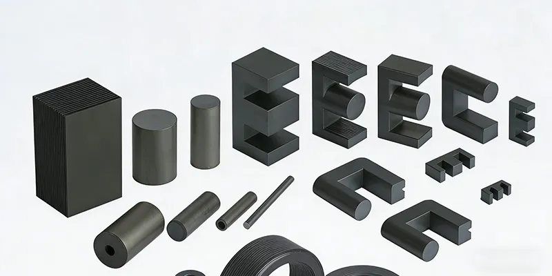
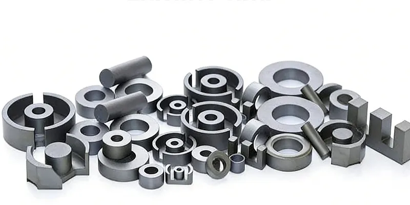
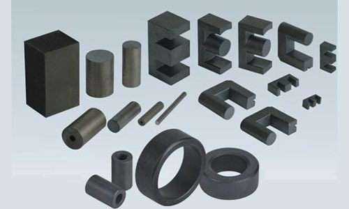
Step 3: Match the Core Geometry to Your Topology
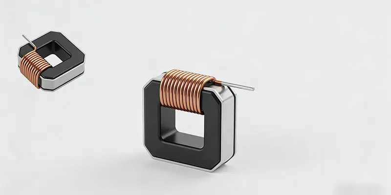
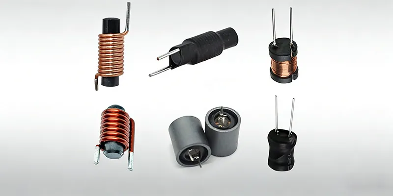
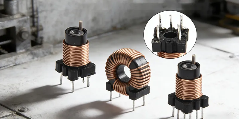
Different magnetic components have different requirements — and core geometries are optimized for specific functions. **Transformer cores** (forward, flyback, push-pull, LLC): - Need good coupling between primary and secondary windings - Need controlled leakage inductance for some topologies - Best geometries: EER, ETD, RM cores **Inductor cores** (output filters, energy storage, PFC): - Need high saturation flux density to handle DC bias current - Typically only one winding (or two loosely coupled) - Best geometries: PQ, toroidal, DN (double-cylinder) **Common-mode chokes**: - Need high permeability for maximum impedance at low frequencies - Usually single-winding (or bi-winding) - Best geometries: toroidal, bin-core, or RM type Choosing the wrong geometry for your component type is one of the most common mistakes in magnetic design.Step 4: Evaluate Key Specifications
Once you've narrowed candidates by frequency, power, and geometry, evaluate these parameters: **Initial Permeability (μi)** Higher permeability means more inductance per turn — useful for filter inductors and common-mode chokes. Lower permeability materials (like 2G8 with μi ≈ 2500) are better for power transformers because they saturate less readily under DC bias. **Saturation Flux Density (Bsat)** The flux density at which the core's magnetic performance begins to degrade. Higher Bsat is always better for power applications — it means you can achieve a given inductance with fewer turns, which reduces copper loss and footprint. **Core Loss (Pcv)** Power loss per unit volume, typically measured at 100°C, 100 kHz, 100 mT. Compare at your actual operating conditions, not just catalog values. Material grades optimized for power conversion (2G8) show significantly lower losses than high-permeability grades (2H5) in the 50–200 kHz range. **Curie Temperature (Tc)** The temperature at which the ferrite loses all magnetic properties. For industrial applications with poor thermal management, leave adequate margin between your maximum operating temperature and Tc. For automotive under-hood use, specify cores with Tc at least 50°C above your maximum expected temperature.Step 5: Verify Mechanical Fit
Often overlooked but critical: **Dimensions**: Check all critical dimensions — especially the center post diameter (for bobbin fit) and the mounting hole pattern. Catalog drawings show dimensions in mm, and not all cores from different manufacturers use identical pin layouts even if the core geometry is similar. **Bobbin availability**: For standard EER and ETD cores, bobbins are widely available from multiple manufacturers. For unusual geometries or sub-miniature cores, bobbin availability may be limited or require custom tooling. **Mounting method**: Does the core need to be surface-mounted, PCB-through-hole, or chassis-mounted? Thermal interface material between core and heatsink matters for high-power designs.Step 6: Cross-Referencing Between Manufacturers
When substituting one manufacturer's core for another, the key parameters to match are: 1. **Dimensions** — Ae, le, Ve, and window area must be within ±10% 2. **Material grade** — initial permeability and loss characteristics 3. **Temperature grade** — Curie temperature and thermal stability TOMITA provides a cross-reference table mapping their materials to approximate equivalents from TDK, FDK, Cosmo, and other major manufacturers. Use these as a starting point for substitution, then validate thermally in your actual circuit.Common Mistakes to Avoid
**Mistake 1: Prioritizing initial permeability over loss performance** High-μi materials look attractive on paper, but they often have higher losses at power frequencies. For power transformers, medium-permeability power grades consistently outperform high-μi materials thermally. **Mistake 2: Ignoring DC bias effects** Catalog permeability is measured at zero DC bias. In inductor applications with significant DC current, effective permeability drops substantially. Always check the AL vs. DC bias curve for your material, not just the initial permeability specification. **Mistake 3: Designing right to the catalog Bsat** Bsat is specified at room temperature. At elevated temperatures (especially above 100°C), effective Bsat drops significantly. Design your maximum flux density at your worst-case hot operating temperature, not at 25°C. **Mistake 4: Assuming all manufacturers measure the same way** Material grades aren't fully standardized. Permeability and loss measurements can vary slightly between manufacturers' test conditions. When switching suppliers, validate performance in-circuit rather than trusting catalog equivalency alone.Summary: The Quick Selection Checklist
Before finalizing your selection, confirm: - [ ] Operating frequency matches the material grade - [ ] Power level fits the core size - [ ] Geometry matches the component function (transformer vs. inductor vs. choke) - [ ] Maximum flux density at operating temperature is below 70% of Bsat - [ ] Calculated temperature rise is within acceptable limits - [ ] Dimensions fit the mechanical envelope - [ ] Bobbin and mounting hardware are available - [ ] Thermal interface to heatsink/chassis is manageable For technical support on core selection for your specific application, contact the GRXElec engineering team. We can provide samples, simulation support, and cross-referencing assistance for TOMITA and other major ferrite brands.Shenzhen Gaorunxin Technology Co., Ltd