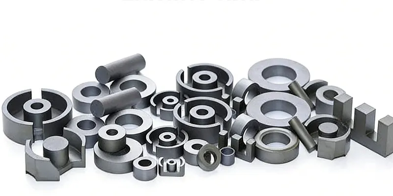


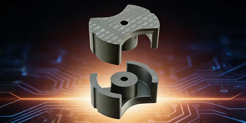
How to Select the Right Ferrite Core for Your Power Supply Design
Ferrite core selection is one of the most consequential decisions in power supply design. Choose correctly and your switch-mode power supply (SMPS) runs cool, efficient, and within regulatory EMI limits. Choose poorly and you face saturation, thermal runaway, or failing compliance tests.
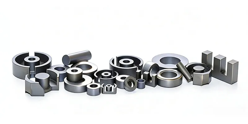
Start With Operating Frequency
The two primary ferrite families — MnZn (Manganese-Zinc) and NiZn (Nickel-Zinc) — serve fundamentally different frequency ranges:
- MnZn: 20 kHz to ~3 MHz. High permeability, low core loss at medium frequencies. The default choice for SMPS transformers and inductors.
- NiZn: 1 MHz to several hundred MHz. Lower permeability but superior high-frequency loss characteristics. Ideal for EMI suppression beads and RF applications.
Operating a MnZn core above its optimal frequency band causes losses to spike dramatically. Conversely, using NiZn at power frequencies wastes material cost and size.
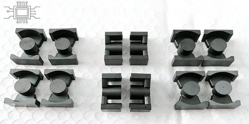
The Area-Product Method for Core Sizing
For a given power level and switching frequency, estimate minimum core size using the area-product equation:
Ap = (Pt × 10⁴) / (4.44 × f × Bmax × Kc)
Where Ap is area product (cm⁴), Pt is total power (W), f is switching frequency (Hz), Bmax is maximum flux density (typically 200–300 mT for ferrites), and Kc is window fill factor (0.3–0.5).
Select a core whose area product equals or exceeds this calculated value. Then validate against the manufacturer's datasheet — thermal constraints often demand a larger core than the pure calculation suggests.
Saturation Margin: The Non-Negotiable
Ferrite cores saturate abruptly. Unlike iron powder, there is no gradual roll-off. Design for at least 30% saturation margin at maximum operating temperature. As temperature rises, saturation flux density drops — so your worst-case thermal scenario must be accounted for in the margin calculation.
Thermal Rise and Winding Window
The window area must accommodate the required turns while leaving space for insulation and heat dissipation. Excessive winding density drives temperature up, which degrades core performance in a feedback loop. Target a temperature rise of 40°C or less under full load.
Match Loss Profile to Application Type
Core losses have two components: hysteresis loss (proportional to frequency and flux density) and eddy current loss (proportional to frequency squared). At higher frequencies, eddy currents dominate. For continuous conduction mode (CCM), prioritize low hysteresis loss grades. For DCM, both mechanisms matter equally.
Conclusion
Ferrite core selection is multidimensional but not arbitrary. Begin with the area-product calculation, verify against manufacturer datasheets, always derate for temperature, and maintain meaningful saturation margin. Getting this right avoids costly respins and field failures.
Shenzhen Gaorunxin Technology Co., Ltd