Welcome to our company!


Magnetic Component Design Guide for Communications Power Supplies
Technical guide covering ferrite core and material selection for telecom power supplies, including LLC transformers, PFC inductors, output filters, and EMI common-mode chokes.
2026-03-28 22:33
Magnetic Component Design Guide for Communications Power Supplies
Share
# Magnetic Component Design Guide for Communications Power Supplies Communications infrastructure — from base station power supplies to data center rectifiers — demands magnetic components that combine high efficiency, high power density, and exceptional reliability. These power supplies often operate 24/7 at high load factors, making thermal management and efficiency optimization critical. This guide covers the key considerations for designing magnetic components in communications power applications, with focus on the ferrite cores and materials that perform best in this demanding environment.
Why Communications Power is Different
Communications power supplies have distinct requirements that set them apart from consumer electronics: **Continuous operation**: Unlike consumer adapters that spend most of their time idle, telecom power supplies often run at 80–100% load continuously. Every watt of loss is multiplied across thousands of operating hours per year. **High efficiency mandates**: 98%+ efficiency is increasingly the standard for telecom rectifiers. At these efficiency levels, a 1% improvement represents significant energy savings across a network of equipment. **Thermal constraints**: Equipment is often installed in confined spaces with limited airflow — base station shelters, outdoor cabinets, data center racks. Heat dissipation is constrained, making efficiency directly tied to thermal viability. **Reliability requirements**: A base station power failure means a service outage. Components must operate reliably for 10+ years with minimal failure rates. **EMI robustness**: Communications equipment must coexist with sensitive radio receivers. Switching noise from the power supply can degrade signal quality if not adequately filtered.Ferrite Materials for Communications Power
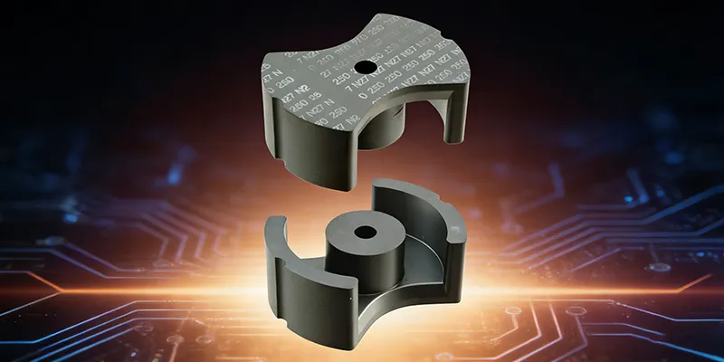
For telecom power supplies operating at typical switching frequencies (50–250 kHz), TOMITA's 2G8 and 2G8A materials offer the best balance of low loss and temperature stability. **TOMITA 2G8**: The workhorse for telecom power applications. Low loss at 100–200 kHz, stable across temperature, and available in all standard geometries. Suitable for rectifiers from 500W to 5kW. **TOMITA 2G8A**: An enhanced version with improved loss characteristics at higher flux densities. The preferred choice for ultra-efficient designs (98%+) where every fraction of a percent matters. For very high frequency stages (above 500 kHz) in GaN-based designs, TOMITA 6G8 or 4A3 (Ni-Zn) materials provide the low-loss performance needed at these frequencies.Transformer Design for Telecom Rectifiers
Sizing Considerations
Telecom rectifiers typically use LLC or phase-shift full-bridge topologies, both of which benefit from resonant switching to minimize switching losses. This has direct implications for magnetic design: **LLC transformers** operate at resonance, where the switching frequency tracks the resonant frequency of the LC network. The transformer sees approximately sinusoidal voltage and current waveforms, which means lower peak flux for the same power compared to hard-switched topologies. **Phase-shift full-bridge** transformers see square-ish waveforms but with zero-voltage switching (ZVS) at turn-on, reducing switching losses. The magnetic design must still handle the full power transfer with adequate saturation margin.Core Selection
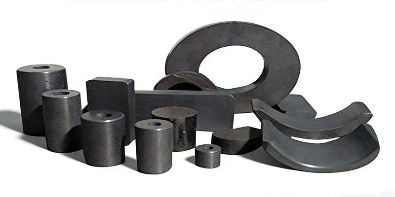
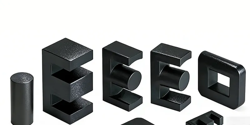
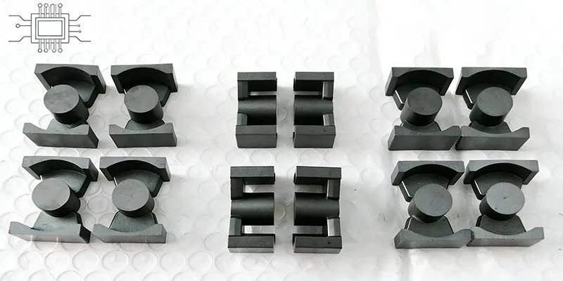
For LLC transformers in the 1–5kW range, ETD cores are the most common choice: - **ETD-39** — good for 1–2kW designs - **ETD-44** — handles 2–3kW - **ETD-49** or **EER-49** — for 3–5kW designs For phase-shift full-bridge transformers, EER or ETD geometries both work well. The key is ensuring adequate window area for the high-current secondary windings — telecom rectifiers often output 48V or 54V at 20–50A, requiring heavy copper or multiple parallel conductors.Winding Design
High-current windings in telecom transformers demand careful attention: **Litz wire or foil**: For currents above 10A secondary, consider Litz wire to minimize skin effect losses at the switching frequency. Alternatively, copper foil provides good utilization of the window area and excellent thermal conductivity. **Interleaving**: For transformers with multiple secondary windings, interleaving (alternating primary and secondary layers) dramatically reduces leakage inductance — critical for LLC applications where leakage directly impacts resonant behavior. **Thermal management**: Terminate windings with adequate margin to the core edge for thermal transfer. In high-reliability telecom applications, thermal runaway from copper loss is a real risk in confined installations.Output Inductor Design
PFC Boost Inductors
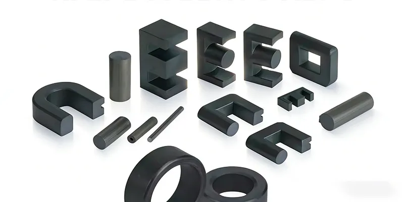
Telecom rectifiers typically include an input PFC stage to achieve high power factor and compliant current harmonics. The PFC inductor must handle continuous AC waveform at mains frequency (50/60 Hz) while also managing the switching frequency ripple current. At 50/60 Hz, the core flux is dominated by the mains frequency, not the switching frequency. This means: - Core loss is minimal — thermal constraints come from copper loss - Material permeability matters less than saturation margin - The AC flux swing is relatively small compared to the DC bias from the average current For PFC inductors, TOMITA 2G8 material in PQ or E-core geometries provides adequate performance. The key selection parameter is saturation margin — ensure the core can handle peak AC current without saturation while remaining within thermal limits.Output Filter Inductors
After the rectification stage, output filter inductors smooth the current waveform to meet ripple specifications. These inductors operate at the switching frequency with DC current bias from the load. Key selection criteria: - **AL value** at the required DC bias current — not just initial AL - **Saturation flux density** sufficient for peak load current - **Thermal stability** — losses must be manageable in the installation environment For telecom rectifiers with 48V outputs at 50–100A, PQ cores with 2G8 material are typically used, with careful thermal interface to the equipment chassis.EMI Filtering with Common-Mode Chokes
Why EMI Matters in Telecom
Base station equipment includes sensitive radio receivers operating alongside digital processing electronics. Switching power supply noise — conducted through power cables or radiated directly — can desensitize receivers or cause demodulation of wanted signals. The regulatory requirements (EN 55032, FCC Part 15, CISPR 32) mandate conducted and radiated emissions limits. Meeting these limits while maintaining high efficiency is one of the core challenges in telecom power design.Common-Mode Choke Design
Common-mode chokes suppress the noise currents that flow on both the line and neutral conductors in the same direction (or on the positive and negative rails in DC systems). For telecom power supplies, common-mode chokes must provide high impedance across a wide frequency range — from 150 kHz (the conducted emissions measurement lower limit) up to 30 MHz or higher. Material selection is critical: - High permeability materials (TOMITA 2H5, μi ≈ 3700) provide maximum impedance at low frequencies - For wideband filtering, consider dual-material designs — a high-permeability core for low-frequency attenuation, or multiple chokes with different materials at different positions in the EMI filter The trade-off with high-permeability chokes: they are more susceptible to saturation from asymmetric fault currents. Size the core to avoid saturation during fault conditions, not just normal operation.Thermal Management Best Practices
In telecom installations, magnetic components are often the thermal bottleneck. Consider these practices: **Use thermal interface material (TIM)**: Apply thermally conductive silicone or phase-change material between the core and chassis. The thermal resistance of the air gap without TIM can dominate the total thermal resistance. **Considerfan cooling**: If the application allows, even low-speed forced-air cooling dramatically improves thermal performance. A 10°C reduction in core temperature roughly doubles the lifetime of electronic insulation systems. **Distribute losses**: In high-power systems, don't concentrate all the magnetic components in one area. Distribute them to allow natural convection or forced air to cool each component. **Account for derating**: Most ferrite manufacturers specify performance at 100°C. If your installation ambient exceeds 50°C, derate core performance accordingly — the useful AL value and saturation margin both decrease with temperature.Reliability Considerations
For 10+ year telecom deployments, magnetic component reliability requires attention to: **Thermal cycling**: Base station outdoor cabinets experience wide temperature swings — from sub-zero in winter to 50°C+ in summer. This causes repeated expansion/contraction that can crack poorly mounted cores or damage winding insulation. Use compliant mounting methods (silicone vibration damping, flexible thermal pads) and specify components with documented thermal shock resistance. **Corrosion resistance**: Outdoor cabinets in humid or coastal environments can expose components to moisture. Specify ferrite cores with appropriate coatings or select bobbins and housings that provide moisture protection. **Screening and derating**: For critical infrastructure, consider thermal screening of magnetic components to identify infant mortality failures. Derating components below their catalog maximum ratings also improves long-term reliability.Conclusion
Communications power supplies place demanding requirements on magnetic components — continuous high load, excellent efficiency, thermal management challenges, and long lifetime expectations. Success requires careful attention to material grade selection, core geometry, thermal design, and reliability engineering. For telecom power magnetic design support, including core selection, sample provision, and custom geometry development, contact the GRXElec engineering team.Shenzhen Gaorunxin Technology Co., Ltd