Welcome to our company!


Transformer Cores vs. Inductor Cores: Understanding the Differences
Explains the fundamental magnetic differences between transformers and inductors, and how to select the right core geometry and material grade for each application type.
2026-03-28 22:33
Transformer Cores vs. Inductor Cores: Understanding the Differences
Share
# Transformer Cores vs. Inductor Cores: Understanding the Differences and Selection Criteria One of the most frequent sources of confusion in magnetic component design is the difference between transformer cores and inductor cores. Both involve ferrite cores and copper windings, but the magnetic requirements are fundamentally different — and using the wrong core type for your component can sabotage an otherwise well-designed circuit. This article explains the key differences, helps you identify which you need, and covers selection criteria for each.
The Core Difference: Magnetism Direction
The fundamental difference is how the magnetic flux behaves in the core: **In a transformer**, the AC flux swings symmetrically around a bias point. The current in the primary creates flux that couples to the secondary — energy is transferred magnetically without net DC offset. The flux swing is bipolar (alternating above and below zero). **In an inductor**, the flux is biased by DC current and swings asymmetrically. There's a DC offset from the average current, and the AC component rides on top of that DC bias. The flux never crosses zero — it goes from B_max down to some minimum value determined by the load current. This difference has massive implications for core selection.Why Transformers Need Different Cores
Transformers transfer energy using Faraday's Law — the rate of change of flux determines the induced voltage. For a given applied voltage and frequency, the flux swing (ΔB) is fixed by the core geometry: ΔB = (V × t_on) / (N × Ae) Where V is the applied voltage, t_on is the switch conduction time, N is turns, and Ae is the cross-sectional area. Since V and t_on are determined by the circuit topology and frequency, and Ae is fixed by the core you choose, N is the only free variable. More turns means lower ΔB — but more copper, higher resistance, and more copper loss. The key constraint for transformer cores is avoiding saturation during transients (such as startup or load steps) while keeping ΔB high enough for reasonable efficiency and size.Why Inductors Need Different Cores
Inductors store energy in a magnetic field. The stored energy is: W = (1/2) × L × I² For a given inductance L and current I, you need a core with sufficient AL value (inductance factor, in nH/turn²). But unlike transformers, inductors must handle DC bias current without saturating. The DC bias causes the effective permeability to drop — often dramatically. A core with μi = 2500 at zero bias might behave like μi = 800 at the DC current your design requires. This is why inductor cores typically use materials with lower initial permeability but better DC bias characteristics.Core Geometry Comparison
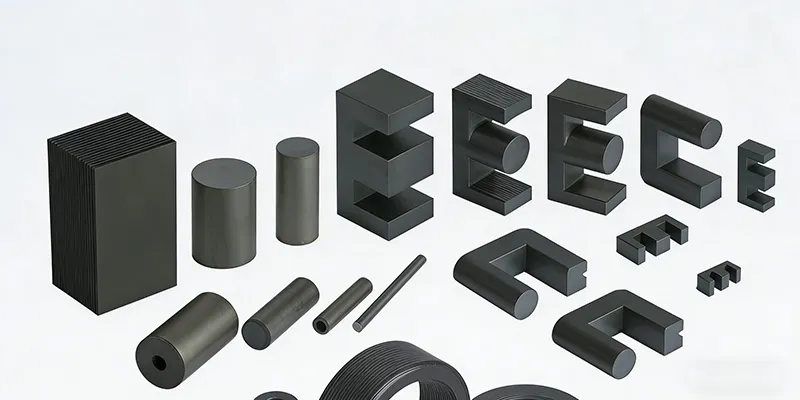
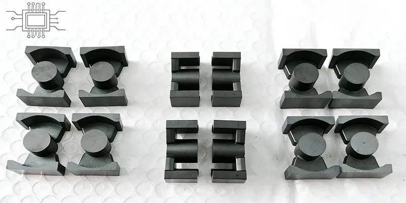
| Geometry | Best For | Why |
|---|---|---|
| **EER** | Transformers (flyback, forward) | Good Ae/Aw ratio, excellent coupling, standard bobbins |
| **ETD** | Transformers (half-bridge, LLC) | Low profile, larger window for high-current designs |
| **PQ** | Power inductors, output filters | Maximized Ae for high saturation threshold |
| **RM** | Compact transformers & inductors | Good coupling + moderate window area |
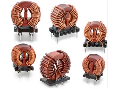
| **Toroidal** | EMI chokes, common-mode | Self-shielding, minimal EMI radiation |
| **U/I or E/I** | Low-cost transformers | Simple, inexpensive, widely available |
Material Selection: Transformer vs. Inductor
For transformers operating below 300 kHz, TOMITA's 2G8 grade is typically optimal — it offers low loss at power frequencies with good temperature stability. For inductors where DC bias is a factor, TOMITA's 2G8A or 6G8 grades provide better saturation characteristics. The 6G8 grade, in particular, maintains usable permeability at high DC bias levels, making it suitable for power inductors in high-current converters. For common-mode chokes, where maximum impedance at minimum frequency is the goal, high-permeability grades like TOMITA 2H5 (μi ≈ 3700) are standard. However, these cores must be sized to avoid saturation from the maximum fault current the system might experience.Key Selection Criteria by Application Type
Flyback Transformer
- Core geometry: EER or RM - Material: 2G8 (power grades) - Key sizing parameter: Product of primary inductance and peak current - Watch out for: Core saturation during load transientsForward Converter Transformer
- Core geometry: EER or ETD - Material: 2G8 - Key sizing parameter: Volt-second product per cycle - Watch out for: Flux reset during the freewheeling periodOutput Filter Inductor (continuous conduction mode)
- Core geometry: PQ or toroidal - Material: 2G8 or 6G8 (depending on frequency) - Key sizing parameter: Inductance required at peak DC bias current - Watch out for: Saturation at peak load currentPFC Inductor
- Core geometry: PQ or EER - Material: 2G8 - Key sizing parameter: Inductance needed at AC mains frequency (50/60 Hz), but with AC waveform riding on DC bias - Watch out for: Combined AC and DC flux — the DC bias can be significantCommon-Mode Choke
- Core geometry: Toroidal or bin-core - Material: 2H5 (high permeability) - Key sizing parameter: Impedance at target EMI frequency - Watch out for: Saturation during differential-mode surge eventsCan You Use a Transformer Core as an Inductor?
Generally no — or at least, not optimally. Transformer geometries (EER, ETD) are designed to maximize coupling between windings, which means they have relatively low effective magnetic path length. When used as an inductor with significant DC bias, the flux is concentrated in a small cross-section, pushing toward saturation quickly. Conversely, inductor geometries (PQ, toroidal) have magnetic paths that are less sensitive to DC bias. Using a PQ core as a transformer is possible but typically results in higher leakage inductance and larger form factor than necessary.A Note on Dual-Use Cores
Some geometries (RM cores in particular) can serve both transformer and inductor functions, which makes them useful in multi-output power supplies where you need one core to serve both roles. However, they are optimized for neither — so in high-performance single-function designs, use the geometry that's purpose-built for your application.Practical Example
Suppose you're designing a 100W flyback converter for a 24V output, operating at 100 kHz, with a 400V input bus. For the transformer: - Use an EER-35 or ETD-34 core with 2G8 material - Size for approximately 0.3mm² Ae per watt at 100 kHz - Confirm saturation margin at maximum input voltage and minimum load For the output filter inductor: - Use a PQ-2620 core with 2G8 material - Size for required inductance at 3A peak current - Verify that effective permeability at 3A DC bias still provides the required L valueConclusion
Understanding whether you need a transformer core or an inductor core is fundamental — and the choice affects everything from geometry to material grade to thermal performance. The core difference lies in the bipolar flux swing of transformers versus the DC-biased unipolar flux of inductors. When in doubt, consult the GRXElec engineering team. We can help you select the right core geometry and material for your specific power supply topology.Shenzhen Gaorunxin Technology Co., Ltd