

What Is a Floating Connector? Structure, Concept & How It Works
In our previous article, we explored why floating connectors were developed — to overcome the reliability problems that standard board-to-board connectors face under vibration and mechanical stress. But what exactly is a floating connector? Where does the floating come from? And what does the internal structure actually look like?
1. Defining the Floating Connector
A floating connector is a connector built on the foundation of a standard connector, with an added floating structure that allows short-range positional displacement in one or more directions. A standard connector is rigid — once the pins are soldered to the PCB, there is no room for relative movement. A floating connector introduces an elastic floating mechanism that allows a portion of the connector (typically the mating head) to move freely within a defined range.
2. Floating Connectors vs. Standard Connectors
| Dimension | Standard Connector | Floating Connector |
|---|---|---|
| Basic Function | Electrical connection, signal transmission | Same — fully preserved |
| Mechanical Structure | Rigid, no relative motion | Floating structure, allows positional displacement |
| Vibration Resistance | Rigid resistance — relies on structural strength | Elastic absorption — flexible compliance |
| Tolerance Accommodation | Low — high alignment precision required | High — tolerates moderate misalignment |
A floating connector is an upgraded version of a standard connector. It retains all the electrical performance of its standard counterpart while adding a floating mechanism for superior environmental adaptability.
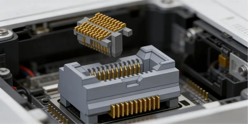
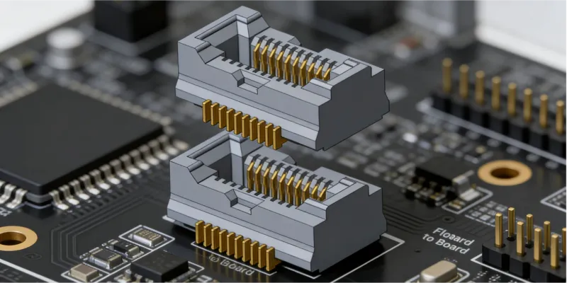
3. The Basic Structure of a Floating Connector
A complete floating connector assembly consists of two parts:
Part 1: The Fixed Side
The fixed side is essentially a standard connector — its pins are soldered directly to the PCB and it has no floating capability. In a floating connector pair, the fixed side is the conventional connector.
Part 2: The Floating Side
The floating side is where the innovation lies. It contains an internal elastic floating mechanism (typically springs or spring-like structures) that allows: the mating head to move freely within its designed range; the floating head to connect to the base through suspension elements such as connecting rods or link chains, with freedom to move within the designed range of motion; stress from external forces (vibration, pressure, misalignment) to be absorbed by the elastic structure rather than being transmitted directly to the solder joints.
4. What Does True Floating Actually Mean?
Not every product marketed as a floating connector actually has genuine floating functionality. In the market, two types of products are sometimes confused:
- Connectors with built-in suspension floating structures — These are true floating connectors. They contain internal elastic mechanisms that actively absorb stress.
- Combinations of a standard fixed connector paired with a floating-capable mating connector — In these cases, only the floating side provides the floating function; the fixed side is just a regular connector.
A true floating connector, in the strictest sense, refers to a connector whose floating side has an inherent elastic floating mechanism built in — not merely a pairing that relies on one partner doing all the work.
5. Three-Axis Floating After Mating
Once the fixed side and floating side are fully mated, the assembled system behaves as follows:
- X/Y Axes (Horizontal) — The floating side can translate freely within the designed range, absorbing horizontal vibration and positional offset
- Z Axis (Vertical) — Some advanced floating connectors also permit displacement along the Z axis, further improving the ability to absorb stress caused by PCB warpage or improper installation
- Elastic Recovery — When the external force is removed, the elastic structure returns the floating side to its center position, restoring connection stability
This three-dimensional floating behavior after mating enables the entire electronic system to maintain stable electrical connections even when subjected to a wide range of mechanical stresses.
6. A Simple Analogy
A floating connector works like a seismic isolation foundation in architecture. An ordinary building (standard connector) is anchored rigidly to the ground — when an earthquake hits, it has no choice but to rely on structural strength to survive. A building with seismic isolation (floating connector) has an elastic buffer layer between its foundation and the superstructure — earthquake energy is gradually absorbed and dissipated as it travels upward, dramatically reducing the impact on the building above. The same principle applies: a floating connector is the seismic isolation foundation of the PCB interconnect world.
Conclusion
The core concept of a floating connector is straightforward: add an elastic floating mechanism to a standard connector, transforming a rigid, fixed connection into a flexible, shock-absorbing one. This seemingly small structural change delivers a profound leap in connection reliability.
Shenzhen Gaorunxin Technology Co., Ltd