1025FA10-R 10 A 250 Vac Fast-Acting Ceramic Fuse
- Product Details
- Download
1025FA10-R 10 A 250 Vac Fast-Acting Ceramic Fuse
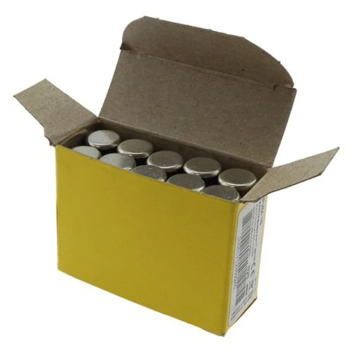
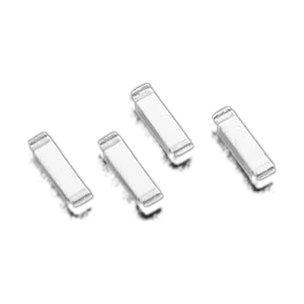
Supplied as TR2/1025FA10-R - 2,500 pieces on 24 mm tape-and-reel, one 13 inch (330 mm) reel.
Electrical Specifications
| Part number | 1025FA10-R |
| Ordering code | TR2/1025FA10-R |
| Packaging | 2,500 pcs on 24 mm tape-and-reel, 13 in (330 mm) reel, EIA-481 |
| Design standard | EIA/IS-722 |
| Voltage rating, DC | 60 Vdc |
| Voltage rating | 250 Vac |
| Package | 10.29 x 2.77 mm (4010 imperial / 1025 metric) |
| Typical cold resistance | 0.0072 Ω |
| Interrupting rating | 50 A AC |
| Terminations | silver-plated end terminations, solder immersion compatible |
| Typical melting I2t | 457 A²s |
| Agency approval | UL Recognition, Guide JDYX2, File E19180 (250 mA - 15 A); CSA component acceptance |
| Rated current | 10 A |
| Typical voltage drop | 146 mV |
The Element and the Curve
The element in a chip fuse is a thin film deposited on a ceramic substrate, which is why the I2t can be an order of magnitude lower than a glass tube of the same rating. Low I2t is the whole point - it is what keeps a fault from reaching the semiconductor behind it.
What the Figures Mean
The table describes one operating point. The cold resistance is 0.0072 Ω, which is what the circuit sees before the element warms. Melting takes 457 A²s, so a fault has to deliver that much energy before the element even starts to go. At rated current the drop is 146 mV. Everything else on this page is context for them.
Position in the Range
At this rating the element is carrying real current and the cold resistance is in the tens of milliohms. The fuse no longer affects the circuit in normal operation, but the energy it has to clear on a fault is larger - which is where the interrupting rating starts to matter.
The step below is 1025FA7-R at 7 A, the step above is 1025FA12-R at 12 A. The package and the land pattern are identical across the three; only the element changes.
What the Code Tells You
1025FA is the family, 10 is the current rating - 10 A, written without a decimal point - and -R is the RoHS suffix.
A packaging prefix such as TR2- goes in front of the whole code and changes only the reel quantity.
Fitting and Replacement Notes
The 1025 body is 10.29 x 2.77 mm - noticeably longer than a 1206. On a dense board that extra length is what forces a layout change, so check the land pattern before specifying it as a substitute for a smaller part.
Because the part is not serviceable in the field, the choice is effectively made once. Confirm what the branch actually draws, including the inrush, before the first build - not after the first failure.
Agency Information
UL Recognition, Guide JDYX2, File E19180 (250 mA - 15 A); CSA component acceptance.
For equipment exported to several markets, check each mark separately. The European and North American approvals on this family do not always cover the same current band.
Questions We Get Asked
What does MSL mean for this part?
Moisture sensitivity level - how long the part can sit out of its dry pack before reflow. Parts at MSL 1 have no floor life limit; higher levels need baking or dry storage before the reflow cycle.
Why does the table list a typical voltage drop?
Because the fuse is in series with the load and its resistance is not zero. On a low voltage rail a few hundred millivolts of drop is a real fraction of the headroom, especially at the higher current ratings.
Why is the interrupting rating so much lower than a glass tube fuse?
The body is small and the element has almost no thermal mass, so it cannot quench a large arc. A chip fuse is designed to open before the fault current reaches its peak, not to interrupt a sustained high-current fault.
Design note: the figures above are Technical Data 4322, measured at 25 °C on the reference land pattern. Check the rating against the actual copper area and the ambient inside the enclosure before release.
Mechanical Dimensions

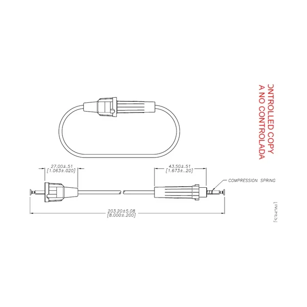
Dimensional drawing and recommended PCB pad layout from the Eaton data sheet. Tolerances and pad dimensions are as printed on the drawing; check the outline against your layout before release.
Shenzhen Gaorunxin Technology Co., Ltd
Online message
Shenzhen Gaorunxin Technology Co., Ltd