

CRMM4805D CR Micro -30V -11A Dual MOSFET SOP-8
- Product Details
- Download
- -30 V / -11 A continuous drain current, SOP-8 package
- Rds(on) 13.5 mΩ typ, 16.2 mΩ max at VGS = 10 V
- Qg 43.4 nC and Ciss 2348 pF
- P-channel, dual configuration
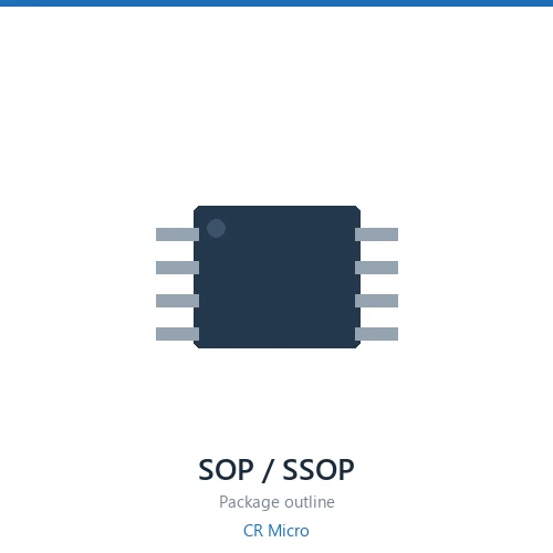
The CR Micro CRMM4805D is a -30 V -11 A P-channel dual MOSFET in a SOP-8 package. The package carries two independent N-channel dies. On-resistance is 13.5 mΩ typical and 16.2 mΩ maximum at a 10 V gate drive; 17.5 mΩ typical at 4.5 V, so it also works from a logic-level driver; threshold voltage spans -1.5 to -2.5 V.
Key Specifications
| Drain-Source Voltage (VDS) | -30 V |
| Continuous Drain Current (ID) | -11 A |
| Circuit Configuration | dual |
| Rds(on) @ VGS = 10 V, typ. | 13.5 mΩ |
| Rds(on) @ VGS = 10 V, max. | 16.2 mΩ |
| Rds(on) @ VGS = 4.5 V, typ. | 17.5 mΩ |
| Gate Threshold Voltage (VGS(th)) | -1.5 – -2.5 V |
| Total Gate Charge (Qg) | 43.4 nC |
| Input Capacitance (Ciss) | 2348 pF |
| Channel Polarity | P |
| Package | SOP-8 |
Same-Rating Selection Table
| Part Number | VDS | ID | Config | Rds 10V typ | Rds 4.5V typ | Qg | Package |
|---|---|---|---|---|---|---|---|
| CRMM4805D | -30V | -11A | dual | 13.5 | 17.5 | 43.4 | SOP-8 |
| CRMM4805D | -30V | -11A | dual | 13.5 | 17.5 | 43.4 | SOP-8 |
| CRMM4953D | -30V | -5A | dual | 50 | 72 | 11.2 | SOP-8 |
| CRMM4953D | -30V | -5A | dual | 50 | 72 | 11.2 | SOP-8 |
4 part numbers share the same -30 / SOP-8 / dual rating — sorted by config.
Applications
Low-voltage DC-DC converters, load switches, battery protection, and brushed or stepper motor drive.
Selection Notes
- The two dies share a package but not a thermal path. Check whether the configuration is complementary, dual, common drain or series before wiring it into a topology.
- In complementary parts the N and P dies have different Rds(on) and Qg. Match the drive separately rather than assuming symmetry.
- Common-drain parts suit load switch and battery protection circuits where the two sources tie together — the body diodes then oppose each other and block in both directions.
- Because both dies sit on one leadframe, total dissipation is limited by the package, not by the individual die ratings.
Common Questions
Is the CRMM4805D an N-channel or P-channel device?
It is P-channel. The drain-source rating is -30 V.
Can the CRMM4805D be driven from a 4.5 V logic-level gate signal?
Yes. The datasheet characterises Rds(on) at 4.5 V: 17.5 mΩ typical and 21 mΩ maximum.
What is the gate threshold voltage of the CRMM4805D?
VGS(th) is specified between -1.5 and -2.5 V. Below the lower figure the part is off; above the upper figure it is fully on at the rated current.
What package does the CRMM4805D come in?
SOP-8. Check the datasheet mechanical drawing for lead spacing and thermal pad dimensions before laying out the footprint.
How do I choose between the 4 part numbers in this rating group?
All 4 share the same voltage and package class. Sort by on-resistance first, then check gate charge: the lowest Rds(on) part is not automatically the best choice if the stage switches at high frequency. The table above lists them in ascending Rds(on) order.
Shenzhen Gaorunxin Technology Co., Ltd
Online message
Shenzhen Gaorunxin Technology Co., Ltd