

CS5N90A8R CR Micro 900V 5A N-Channel MOSFET TO-220
- Product Details
- Download
- 900 V / 5 A continuous drain current, TO-220 package
- Rds(on) 2200 mΩ typ, 2500 mΩ max at VGS = 10 V
- Qg 30.1 nC and Ciss 1156 pF
- N-channel, Planar process
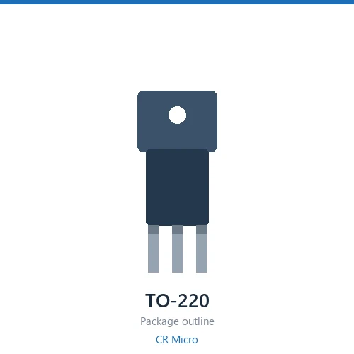
The CR Micro CS5N90A8R is a 900 V 5 A N-channel MOSFET in a TO-220 package, built on the Planar process. On-resistance is 2200 mΩ typical and 2500 mΩ maximum at a 10 V gate drive; gate charge is 30.1 nC with 1156 pF input capacitance; threshold voltage spans 2 to 4 V.
Key Specifications
| Drain-Source Voltage (VDS) | 900 V |
| Continuous Drain Current (ID) | 5 A |
| Rds(on) @ VGS = 10 V, typ. | 2200 mΩ |
| Rds(on) @ VGS = 10 V, max. | 2500 mΩ |
| Gate Threshold Voltage (VGS(th)) | 2 – 4 V |
| Total Gate Charge (Qg) | 30.1 nC |
| Input Capacitance (Ciss) | 1156 pF |
| Channel Polarity | N-channel |
| Process Family | Planar |
| Package | TO-220 |
Same-Rating Selection Table
| Part Number | VDS | ID | Rds(on) typ | Rds(on) max | Qg | Ciss | Package |
|---|---|---|---|---|---|---|---|
| CS6N90A8R-G | 900V | 6A | 1850 | 2300 | 31.1 | 1435 | TO-220 |
| CS5N90A8R | 900V | 5A | 2200 | 2500 | 30.1 | 1156 | TO-220 |
| CS5N90A8RZ-G | 900V | 5A | 2200 | 2500 | 30.1 | 1156 | TO-220 |
3 part numbers share the same 900 / TO-220 / N rating — sorted by rds(on) typ.
Process Technology
Planar — the gate sits flat on the die surface. Lower channel density than trench designs, but a wider safe operating area, stronger avalanche withstand and simpler gate drive. Preferred for high-voltage and rugged industrial loads where robustness outranks on-resistance.
Applications
High-voltage offline supplies, active clamp topologies, and single-stage PFC.
Selection Notes
- Rds(on) rises with junction temperature. Size the heatsink against the hot value given in the datasheet, not the 25 °C number in the table above.
- If the gate is driven below 10 V, check the 4.5 V Rds(on) line — parts without that rating are not characterised for logic-level drive.
- For high-frequency stages compare Qg and Ciss against the Rds(on) gain. A part one bin lower in Rds(on) often costs more switching loss than it saves in conduction.
- The body diode recovery of low-Rds(on) parts can be severe in bridge topologies. Verify dv/dt and dead time against the datasheet before dropping it into a half bridge.
Common Questions
Is the CS5N90A8R an N-channel or P-channel device?
It is N-channel. The drain-source rating is 900 V.
Can the CS5N90A8R be driven at 4.5 V?
No 4.5 V on-resistance figure is published for this part. It is characterised at 10 V gate drive, so use a driver that reaches 10 V.
What is the gate threshold voltage of the CS5N90A8R?
VGS(th) is specified between 2 and 4 V. Below the lower figure the part is off; above the upper figure it is fully on at the rated current.
How much gate charge does the CS5N90A8R need?
Qg is 30.1 nC. Size the driver against that figure at your switching frequency, and add the gate loop loss to the total dissipation budget.
What package does the CS5N90A8R come in?
TO-220. Check the datasheet mechanical drawing for lead spacing and thermal pad dimensions before laying out the footprint.
How do I choose between the 3 part numbers in this rating group?
All 3 share the same voltage and package class. Sort by on-resistance first, then check gate charge: the lowest Rds(on) part is not automatically the best choice if the stage switches at high frequency. The table above lists them in ascending Rds(on) order.
Shenzhen Gaorunxin Technology Co., Ltd
Online message
Shenzhen Gaorunxin Technology Co., Ltd