

CS8N100A8RD-G CR Micro 1000V 8A N-Channel MOSFET TO-220
- Product Details
- Download
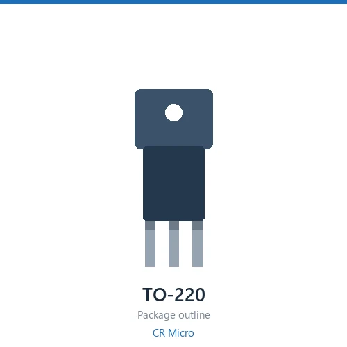
- 1000 V / 8 A continuous drain current, TO-220 package
- Rds(on) 1100 mΩ typ, 1450 mΩ max at VGS = 10 V
- Qg 58 nC and Ciss 2777 pF
- N-channel, Planar process
The CR Micro CS8N100A8RD-G is a 1000 V 8 A N-channel MOSFET in a TO-220 package, built on the Planar process. On-resistance is 1100 mΩ typical and 1450 mΩ maximum at a 10 V gate drive; gate charge is 58 nC with 2777 pF input capacitance; threshold voltage spans 2.5 to 4.5 V.
Key Specifications
| Drain-Source Voltage (VDS) | 1000 V |
| Continuous Drain Current (ID) | 8 A |
| Rds(on) @ VGS = 10 V, typ. | 1100 mΩ |
| Rds(on) @ VGS = 10 V, max. | 1450 mΩ |
| Gate Threshold Voltage (VGS(th)) | 2.5 – 4.5 V |
| Total Gate Charge (Qg) | 58 nC |
| Input Capacitance (Ciss) | 2777 pF |
| Channel Polarity | N-channel |
| Process Family | Planar |
| Package | TO-220 |
Process Technology
Planar — the gate sits flat on the die surface. Lower channel density than trench designs, but a wider safe operating area, stronger avalanche withstand and simpler gate drive. Preferred for high-voltage and rugged industrial loads where robustness outranks on-resistance.
Applications
Solar inverters, three-phase motor drives, UPS, and railway auxiliary converters.
Selection Notes
- Rds(on) rises with junction temperature. Size the heatsink against the hot value given in the datasheet, not the 25 °C number in the table above.
- If the gate is driven below 10 V, check the 4.5 V Rds(on) line — parts without that rating are not characterised for logic-level drive.
- For high-frequency stages compare Qg and Ciss against the Rds(on) gain. A part one bin lower in Rds(on) often costs more switching loss than it saves in conduction.
- The body diode recovery of low-Rds(on) parts can be severe in bridge topologies. Verify dv/dt and dead time against the datasheet before dropping it into a half bridge.
Common Questions
Is the CS8N100A8RD-G an N-channel or P-channel device?
It is N-channel. The drain-source rating is 1000 V.
Can the CS8N100A8RD-G be driven at 4.5 V?
No 4.5 V on-resistance figure is published for this part. It is characterised at 10 V gate drive, so use a driver that reaches 10 V.
What is the gate threshold voltage of the CS8N100A8RD-G?
VGS(th) is specified between 2.5 and 4.5 V. Below the lower figure the part is off; above the upper figure it is fully on at the rated current.
How much gate charge does the CS8N100A8RD-G need?
Qg is 58 nC. Size the driver against that figure at your switching frequency, and add the gate loop loss to the total dissipation budget.
What package does the CS8N100A8RD-G come in?
TO-220. Check the datasheet mechanical drawing for lead spacing and thermal pad dimensions before laying out the footprint.
Shenzhen Gaorunxin Technology Co., Ltd
Online message
Shenzhen Gaorunxin Technology Co., Ltd