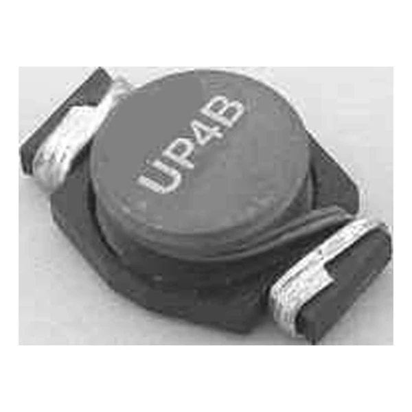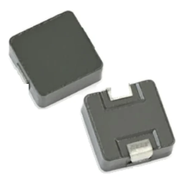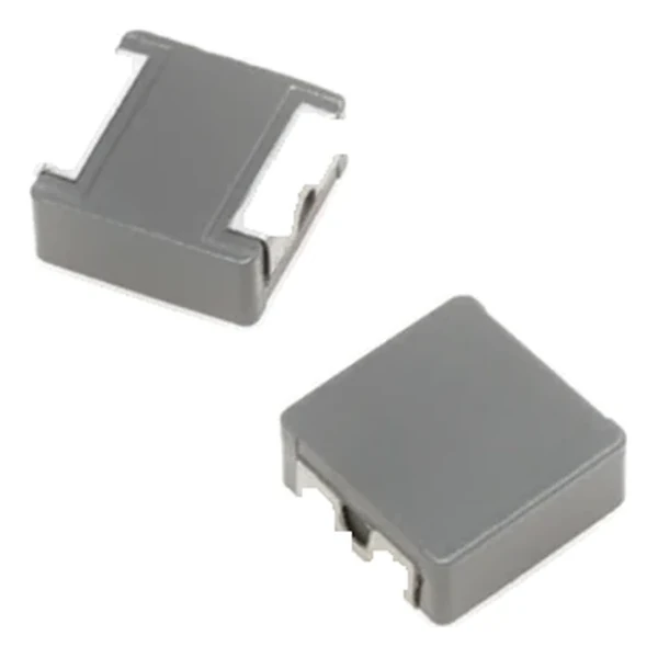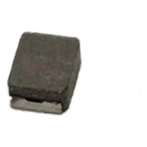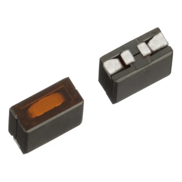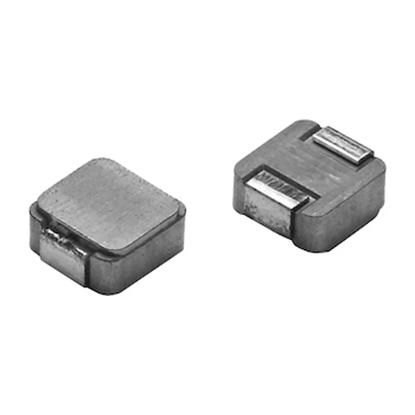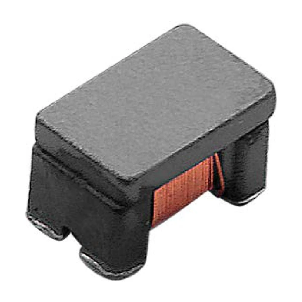
Eaton CLCC1V2012-801-R Common-Mode Noise Suppressor, 800 Ohm
- Product Details
- Download
Eaton CLCC1V2012-801-R Common-Mode Noise Suppressor, 800 Ohm
Product Specifications
| Parameter | Value |
|---|---|
| Orderable part number | CLCC1V2012-801-R |
| Common-mode inductance | 2 uH minimum @ 100 kHz |
| Common-mode impedance | 800 ohm typical (±25%) |
| DCR maximum | 0.88 ohm |
| Rated current | 300 mA |
| Rated voltage | 50 Vdc |
| Withstanding voltage | 125 Vdc |
| Insulation resistance | 10 Mohm minimum |
| Package | 2.0 x 1.2 mm |
| RoHS | Compliant (-R suffix) |
Reading the Data Sheet
The impedance figure is measured across the winding pair, which is exactly the common-mode path. That is why these parts are picked by impedance at the noise frequency rather than by inductance.
Interwinding capacitance is the mechanism behind the high-frequency behaviour: above the capacitance the choke stops blocking and starts passing. Leakage inductance is the part of the inductance that escapes the core and does not help.
Where This Series Fits
CLCC1V2012 是 2.0 x 1.2 mm 共模电感,800 Ohm @100 MHz。
- Typical use: 高速接口、CAN/LIN、以太网差分对滤波.
- 共模电感看的是阻抗不是电感;800 Ohm 的型号衰减强但 DCR 也大,信号完整性要一起算。
- Data sheet ELX1364.
Rated voltage 50 Vdc and 10 Mohm insulation resistance are what make this usable on an automotive bus: the part has to survive the transients and the isolation test without leaking current into the signal.
Frequently Asked Questions
Does it affect my signal?
Only through DCR and the small amount of leakage inductance. The differential signal is not filtered by design.
Why are there two DCR values?
The CMS series specifies each winding separately, measured between (1-2) and between (4-3).
What impedance should I pick?
The one that gives the attenuation you need at the noise frequency of your circuit, then check that the DCR is acceptable on the signal.
Design note: pick the choke by impedance at the noise
frequency, then confirm DCR and rated current against the signal or the rail.
Mechanical Dimensions

Dimensional drawing and recommended PCB pad layout from the Eaton data sheet. Tolerances and pad dimensions are as printed on the drawing; check the outline against your layout before release.
Shenzhen Gaorunxin Technology Co., Ltd
Online message
Shenzhen Gaorunxin Technology Co., Ltd