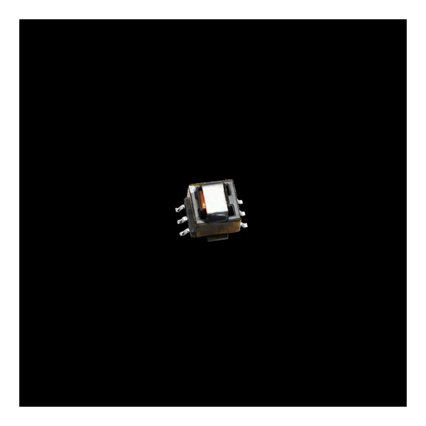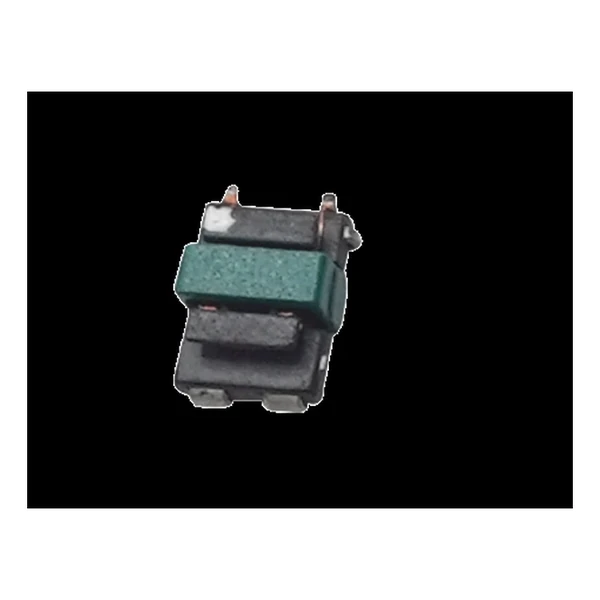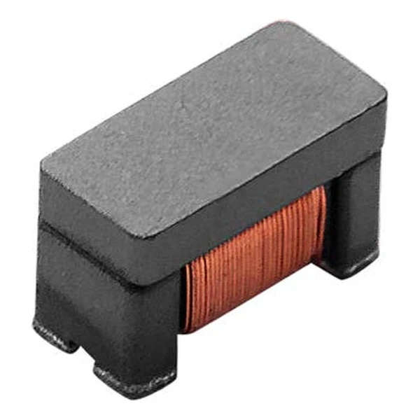
Eaton CLCC2V3216-600-R Capacitive LAN Auto Transformer
- Product Details
- Download
Eaton CLCC2V3216-600-R Capacitive LAN Auto Transformer
Key Specifications
| Parameter | Value |
|---|---|
| Orderable part number | CLCC2V3216-600-R |
| Inductance minimum | 60 uH |
| Inter-winding capacitance maximum | 25 pF |
| DCR maximum @ +25 C | 1.7 Ohm |
| Rated current maximum | 200 mA |
| Rated voltage maximum | 50 Vdc |
| Withstand voltage | 125 Vdc |
| Insulation resistance minimum | 10 MOhm |
| Package | See dimension drawing in the data sheet |
| Mounting | Surface mount |
| Operating temperature | -40 C to +85 C |
| Qualification | Commercial grade |
| RoHS | Compliant, -R suffix |
| Data sheet | Eaton Technical Data ELX1365 |
Outline drawing, winding arrangement and recommended pad layout are on
page 2 of Eaton Technical Data ELX1365; the package line above gives the body size where
the data sheet states it.
Reading the Data Sheet
Capacitive-chip LAN designs replace the usual magnetics module with a chip choke plus a chip auto transformer. This is the transformer half of that pair, and its inter-winding capacitance is what limits how much common mode impedance the pair can present.
60 uH with 25 pF of inter-winding capacitance puts the parallel resonance where the common mode impedance starts to fall away.
Within the CLCC2V3216 family this is item 1 of 1 in the Eaton catalogue.
What This Family Is For
The CLCC chip range is the transformer half of a capacitive-chip LAN front end, in a 1206 case that sits beside the common mode choke.
- The pair only works if the choke and the transformer are characterised together; mixing vendors usually costs common mode margin.
- Typical applications: 1 g, 2.5 g base-t applications; rj45 network interface card; ethernet switch, router, adsl; vdsl digital equipment; network set-top box.
- Design note: inter-winding capacitance sets the top of the common mode band. Ask for the curve, not just the number.
Frequently Asked Questions
Can it be used on the line side?
The rated voltage and withstand voltage on this page are for the PHY side of a capacitive LAN interface. Line-side use needs a part with the appropriate isolation rating.
What limits the common mode impedance?
The inter-winding capacitance. Above the frequency where the capacitance dominates, the choke stops looking like a choke, so the capacitance figure sets the top of the usable band.
Why pair a choke with an auto transformer?
The choke blocks common mode current and the transformer provides the isolation and impedance transformation. Splitting them lets each be a small chip instead of one large module.
Shenzhen Gaorunxin Technology Co., Ltd
Online message
Shenzhen Gaorunxin Technology Co., Ltd