Eaton CTX01-18738-R High Current Coupled Inductor
- Product Details
- Download
Eaton CTX01-18738-R High Current Coupled Inductor
Ratings at a Glance
| Parameter | Value |
|---|---|
| Orderable part number | CTX01-18738-R |
| Open circuit inductance (OCL), 0 Adc | 210 nH |
| Full load inductance (FLL), minimum | 151 nH |
| Irms | 50 A |
| Isat1 | 55 A |
| Isat2 | 45 A |
| DCR typical @ 20 °C | 0.29 mOhm |
| Mounting | Surface mount |
| Operating temperature | -40 °C to +125 °C |
| RoHS | Compliant (-R suffix) |
Reading the Data Sheet
Coupled power inductors for VRM applications are specified as a set with the controller: the turns ratio, the coupling coefficient and the saturation behaviour all feed into the loop. Replacing one with a similar-looking part is not a safe substitution.
The data sheet gives OCL and FLL separately because the core is biased in use. Select on FLL for steady-state ripple, on OCL to identify the part, and on the isolation rating for anything that crosses a boundary.
Coupling is only useful inside the controller it was designed for. Outside that loop the mutual inductance can add to the ripple instead of cancelling it.
Series Positioning
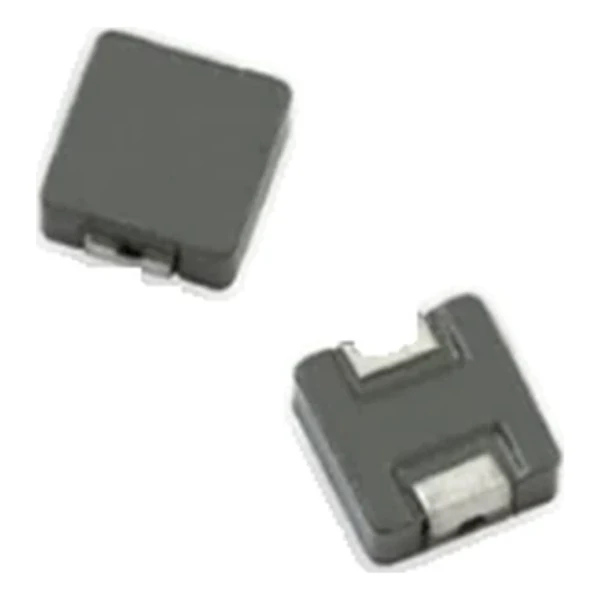
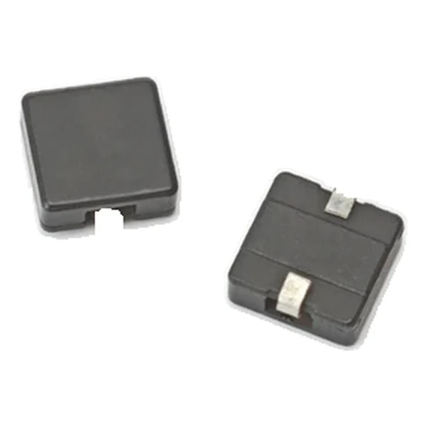
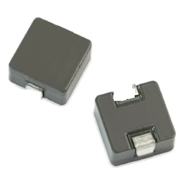
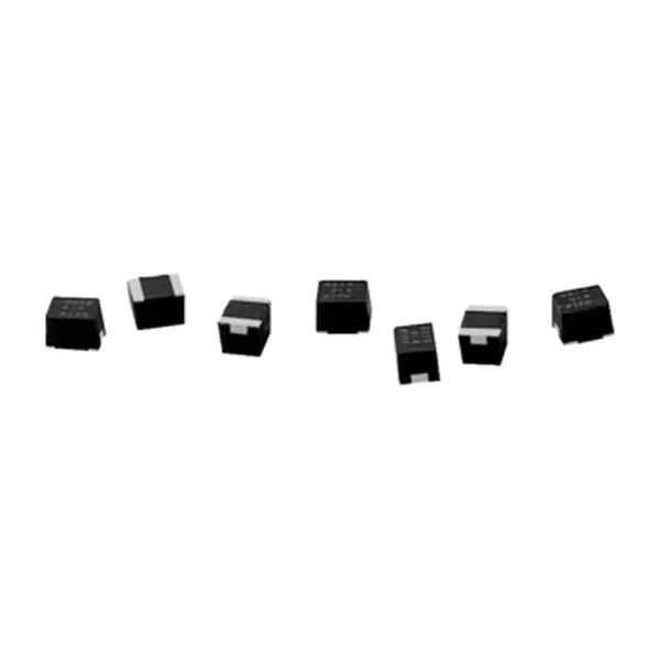
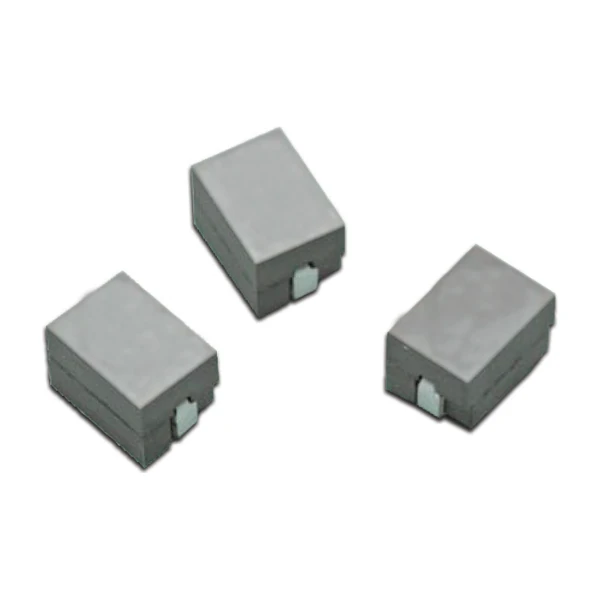
CTX01-18738 is a high-frequency coupled inductor built for multiphase regulators: 210 nH open circuit, 151 nH at full load, and 50 A rms in a surface-mount body.
- Typical applications: VRMs and Vcore regulators, point-of-load modules, base stations, battery systems, graphics cards.
- The gap between OCL and FLL is large on this part; use FLL for ripple and OCL only for identifying the part.
- Data sheet 4410.
Design Notes
210 nH sits at the design point the controller expects of the range, and the trade at that point is explicit: 0.29 mOhm of DCR against 55 A of saturation headroom.
The loss budget is the whole story with a power inductor: core loss grows with frequency and flux swing, copper loss grows with current, and the two meet at a different point for every inductance in the series.
Frequently Asked Questions
Why is there a tolerance on the DCR?
Winding and termination tolerances. Use the maximum for the loss budget.
Is this a transformer or an inductor?
Both, depending on how the windings are used. In the intended controller it is a coupled inductor; the coupling is what cancels ripple.
Is this a transformer or an inductor?
Both, depending on how the windings are used. In the intended controller it is a coupled inductor; the coupling is what cancels ripple.
Design note: the loop compensation assumes this coupling. Do not substitute a part with a different ratio without the controller vendor's blessing.
Mechanical Dimensions

Dimensional drawing and recommended PCB pad layout from the Eaton data sheet. Tolerances and pad dimensions are as printed on the drawing; check the outline against your layout before release.
Shenzhen Gaorunxin Technology Co., Ltd
Online message
Shenzhen Gaorunxin Technology Co., Ltd