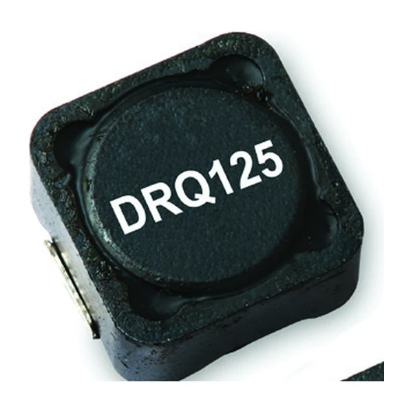
Eaton DRQ125-1R0-R - Dual Winding 1 uH Power Inductor
- Product Details
- Download
Eaton DRQ125-1R0-R - Dual Winding 1 uH Power Inductor
Ratings at a Glance
| Parameter | Value |
|---|---|
| Orderable part number | DRQ125-1R0-R |
| Rated inductance | 1 uH ±20% |
| Open circuit inductance (OCL) | 0.89 uH |
| Irms (40 °C rise) | 15 A |
| Isat | 23.6 A |
| DCR typical @ 20 °C | 2.4 mOhm |
| Volt-microsecond rating | 4.43 V-us |
| Series connection | 3.58 uH, 7.51 A |
| Parallel connection | 1 uH, 15 A |
| Turns ratio | 1:1, coupled |
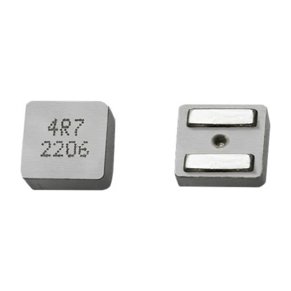
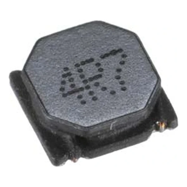
| Package | 12.5 x 12.5 mm footprint, 6.0 mm max height |
| Mounting | Surface mount |
| Operating temperature | -40 °C to +125 °C |
| Qualification | Commercial grade |
| RoHS | Compliant (-R suffix) |
The Figures Explained
One core, two windings, three possible connections. Parallel for current, series for inductance, or coupled as a transformer. The electrical ratings change by roughly a factor of four between the two extreme connections, so the connection is a design decision, not a wiring detail.
Series mode is often mistaken for a way to get more current. It is the opposite - four times the inductance, half the saturation current, twice the DCR. Use it when you need inductance, not when you need amps.
The saturation current is measured at a defined roll-off, and Eaton states the percentage on the data sheet: Isat is the peak current for approximately 30% rolloff at +20 °C. Read the number with the percentage in hand, because "saturation" means different things at 25% and at 40%.
Positioning in the Range
DRQ125 is the 12.5 mm dual-winding part at 6.0 mm height. Wire the windings in parallel for a high-current single inductor, in series for a high-inductance choke, or leave them coupled as a 1:1 transformer for a SEPIC or flyback.
- Typical applications: Desktop and server power, DC-DC converters, SEPIC/flyback transformer use, LCD panels, filter chokes.
- Coupling changes the ripple: a coupled inductor in a multi-phase converter can cancel ripple, but only if the phases are driven with the right duty cycle.
- Data sheet DS4311.
Sizing It Into a Design
At 1 uH this part is in the middle of the family. The winding that produces that inductance is also what sets the 2.4 mOhm DCR - more turns, thinner wire, more resistance.
Efficiency is set by where you sit on the loss curve, and the curve moves with switching frequency. A part that is excellent at 300 kHz can be mediocre at 1 MHz with the same current, because the core loss term takes over.
Frequently Asked Questions
Can I use it as a flyback transformer?
Yes, within the isolation and the 1:1 ratio. Check the reflected voltage and the leakage inductance, because leakage is what creates the spike on the switch node.
What happens if I only use one winding?
The part works as a single inductor, but the unused winding still occupies the core window - you do not get extra saturation headroom by leaving it open.
What happens if I only use one winding?
The part works as a single inductor, but the unused winding still occupies the core window - you do not get extra saturation headroom by leaving it open.
Design note: decide the connection before you lay out the board. Parallel, series and coupled all use the same part, and the inductance moves by 4x between them.
Mechanical Dimensions

Dimensional drawing and recommended PCB pad layout from the Eaton data sheet. Tolerances and pad dimensions are as printed on the drawing; check the outline against your layout before release.
Shenzhen Gaorunxin Technology Co., Ltd
Online message
Shenzhen Gaorunxin Technology Co., Ltd