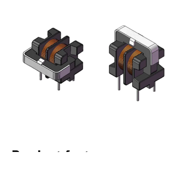
Eaton ECMT1V1714H-500-R Through-Hole Common-Mode Inductor 50 mH
- Product Details
- Download
Eaton ECMT1V1714H-500-R Through-Hole Common-Mode Inductor 50 mH
Key Specifications
| Parameter | Value |
|---|---|
| Orderable part number | ECMT1V1714H-500-R |
| OCL minimum, (1-2) & (4-3) | 50 mH |
| DCR maximum @ +25 °C, (1-2) & (4-3) | 2 Ohm |
| Irms per winding, (1-4) short | 0.5 A |
| SRF minimum | 176 kHz |
| Hi-pot, coil-to-core | 1500 Vac, 2 s, 5 mA |
| Hi-pot, coil-to-coil | 1000 Vac, 2 s, 5 mA |
| Insulation resistance minimum | 100 MOhm |
| Rated voltage | 250 Vac |
| Package | through-hole, closed magnetic path, rated 250 Vac |
| Mounting | Through-hole |
| Operating temperature | -40 °C to +125 °C |
| Qualification | Commercial grade |
| RoHS | Compliant (-R suffix) |
Mechanical Drawing

Drawings from the Eaton data sheet: mechanical outline with rated mm dimensions, recommended PCB pad layout, and winding schematic. Tolerances and pad tolerances are stated on the drawing itself.
The Figures Explained
High impedance and high inductance in a through-hole body: this part exists for power electronics where the noise spectrum is broad and the replacement cycle is measured in years. The independent winding sections mean each line is filtered without cross-talk between them.
The two winding sections are specified separately because a mismatch turns common-mode noise into differential noise. The Hi-pot figures are quoted coil-to-core and coil-to-coil - both are functional isolation ratings, and the 250 Vac rated voltage governs what lines the part may sit between.
Irms is rated per winding with the section short-circuited, which is the harshest thermal case for a common-mode inductor: the whole winding carries the current with no cancellation to help.
Copper loss is the efficiency floor. 2000 mOhm at 25 °C rises about 30% by 100 °C, so the hot-corner budget should use the maximum column, not the typical.
Series Positioning
ECMT is the through-hole common-mode family for industrial power equipment - motion controls, power supplies, solar and wind inverters, chargers - where high isolation and a robust soldered filter point matter more than board area.
- Typical applications: industrial IoT equipment, motion controls, power supplies, battery backup, solar/wind inverters and charger controllers, medical equipment.
- Wave-soldered construction: keep the coil-to-core and coil-to-coil Hi-pot ratings in mind when the two winding sections sit on different circuit domains.
- Data sheet ELX1092; footprint through-hole, closed magnetic path, rated 250 Vac.
Putting It to Work
Frequently Asked Questions
What are the two Hi-pot ratings?
Coil-to-core and coil-to-coil isolation, each tested for 2 seconds at 5 mA. They are functional isolation ratings for circuit architecture, not safety barriers.
What are the two Hi-pot ratings?
Coil-to-core and coil-to-coil isolation, each tested for 2 seconds at 5 mA. They are functional isolation ratings for circuit architecture, not safety barriers.
Why through-hole?
Mechanical robustness and serviceability: the part survives handling, high vibration and wave soldering, which suits industrial power equipment.
Design note: the SRF column is a minimum; the choke stops filtering above it. Match the part to the noise band, not just to the inductance.
Mechanical Dimensions

Dimensional drawing and recommended PCB pad layout from the Eaton data sheet. Tolerances and pad dimensions are as printed on the drawing; check the outline against your layout before release.
Shenzhen Gaorunxin Technology Co., Ltd
Online message
Shenzhen Gaorunxin Technology Co., Ltd