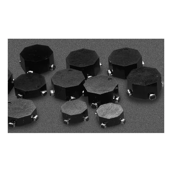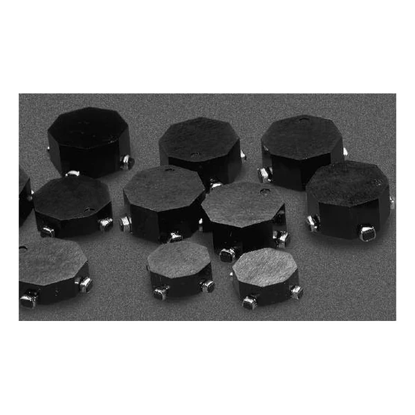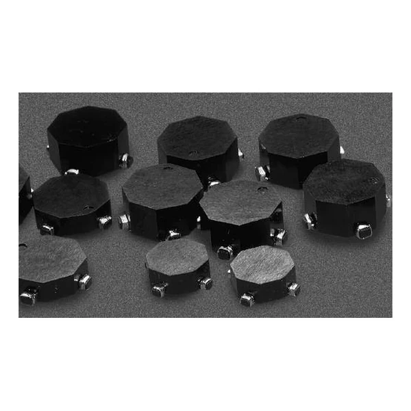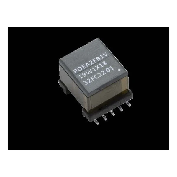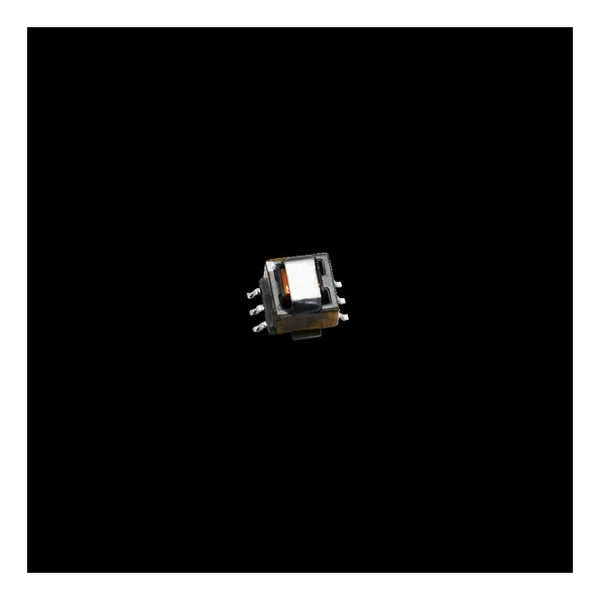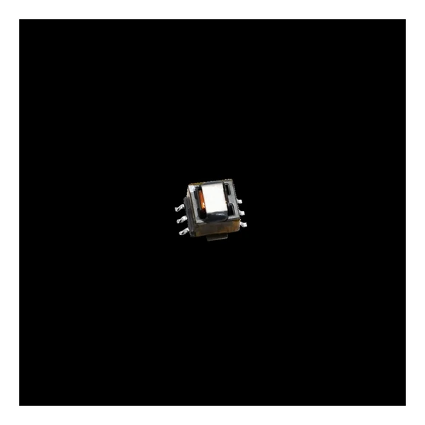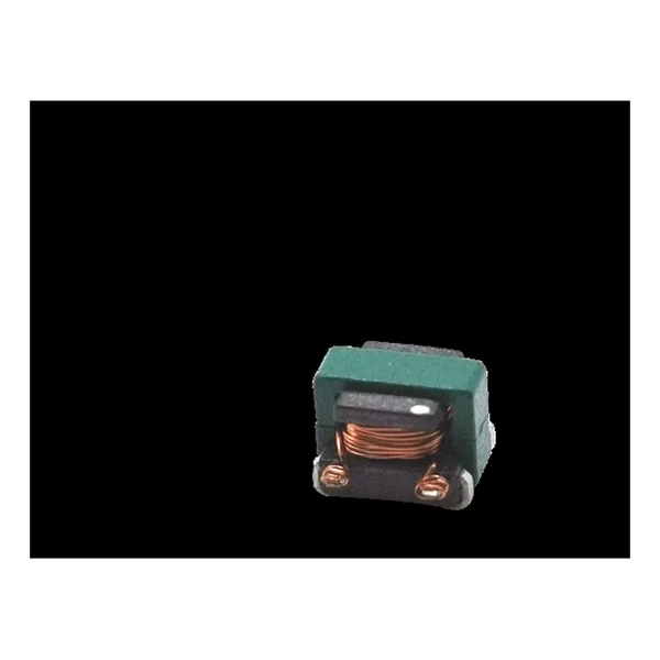
Eaton ECST1V0504-1050-R Current Transformer 50:1
- Product Details
- Download
Eaton ECST1V0504-1050-R Current Transformer 50:1
Key Specifications
| Parameter | Value |
|---|---|
| Orderable part number | ECST1V0504-1050-R |
| Turns ratio secondary:primary | 50:1 |
| Secondary inductance minimum | 205 uH |
| DCR secondary maximum | 2.5 Ohm |
| DCR primary reference | 3 mOhm |
| Hi-pot primary to secondary | 500 Vac |
| Sensed current maximum | 7 A |
| Package | 4.8 x 3.65 x 3.55 mm |
| Mounting | Surface mount |
| Operating temperature | -40 C to +125 C |
| Qualification | Commercial grade |
| RoHS | Compliant, -R suffix |
| Data sheet | Eaton Technical Data ELX1185 |
Outline drawing, winding arrangement and recommended pad layout are on
page 2 of Eaton Technical Data ELX1185; the package line above gives the body size where
the data sheet states it.
How to Read These Ratings
The primary is a single turn – often just a trace or a busbar through the part – and the secondary is the wound coil. That is why the primary DCR is quoted in milliohm and the secondary DCR in ohm: the two sides are built completely differently.
With a 50:1 ratio, a 10 A primary current becomes 0.2 A in the secondary. Across a 50 ohm burden that is 10 V, which is what the controller actually sees.
The secondary winding of 205 uH with 2500 mOhm of resistance sets both the low-frequency corner and the signal loss; both move if you change the burden resistor.
Within the ECST1V0504 family this is item 4 of 9 in the Eaton catalogue.
Where This Series Fits
The ECST and ECSTA ranges cover 7 A to 15 A of primary current in EE4.4 to EE8.3 packages, with turns ratios from 20:1 to 200:1.
- Never operate with the secondary open. Terminate into the burden resistor before applying primary current.
- Typical applications: switching power supplies; feedback control; overload sensing; load drop/shut down detection.
- Design note: the burden resistor and the secondary inductance set the bandwidth. Size the resistor first.
Frequently Asked Questions
Why must the secondary be terminated?
The part is a current source. Left open, the secondary voltage rises until the core saturates or the insulation breaks down; the burden resistor is part of the circuit, not an optional extra.
Why must the secondary be terminated?
The part is a current source. Left open, the secondary voltage rises until the core saturates or the insulation breaks down; the burden resistor is part of the circuit, not an optional extra.
Why must the secondary be terminated?
The part is a current source. Left open, the secondary voltage rises until the core saturates or the insulation breaks down; the burden resistor is part of the circuit, not an optional extra.
Shenzhen Gaorunxin Technology Co., Ltd
Online message
Shenzhen Gaorunxin Technology Co., Ltd