Eaton HC2LP-4R7-R Foil-Wound Inductor 4.55 uH, Isat 21.2 A
- Product Details
- Download
Eaton HC2LP-4R7-R Foil-Wound Inductor 4.55 uH, Isat 21.2 A
Ratings at a Glance
| Parameter | Value |
|---|---|
| Orderable part number | HC2LP-4R7-R |
| OCL (open circuit inductance) | 4.55 uH ±20% |
| Irms (DC, 40 °C rise) | 17 A |
| Isat (20% rolloff @ +25 °C) | 21.2 A |
| DCR typical @ +20 °C | 4.6 mOhm |
| Volt-time rating (V-us) | 20.6 |
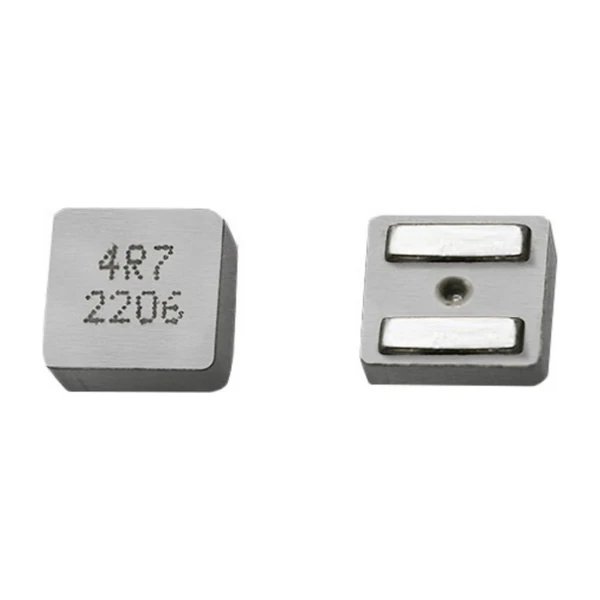
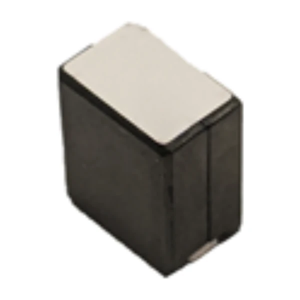
| Package | 19.2 x 19.2 mm |
| Height | 11.18 mm |
| Mounting | Surface mount |
| Operating temperature | -40 °C to +125 °C (ambient plus self-heating) |
| Qualification | Commercial grade |
| RoHS | Compliant, -R suffix |
| Data sheet | Eaton Technical Data 4114 |
Dimensions and Pad Layout

Drawing reproduced from Eaton Technical Data 4114: outline with
rated mm dimensions, recommended pad layout and winding schematic. Tolerances are stated on
the drawing itself.
How to Read These Ratings
A foil winding on a ferrite core is the classic answer to a hard combination: several tens of amps, a supply below 5 V, and a switching frequency high enough that skin depth has already eaten into round wire. The flat conductor keeps the window utilisation high, so DCR stays in the fractions of a milliohm.
Copper loss at the rated current works out to roughly 1.33 W from a typical DCR of 4.6 mOhm at 17 A. It is the number to start a thermal stack-up with, before core loss and before AC resistance rise.
The Isat column is 20% rolloff @ +25 °C. Note what it does and does not mean: it is a defined rolloff point, not a destruction limit. Above it the inductance continues to fall, which is why the transient peak current should be checked against the curve, not just against the number.
At Isat the part holds about 1,027 uJ. On a multiphase rail that is the energy per phase available to bridge a load step, which sets how much bulk capacitance the controller still needs.
What This Family Is For
The HC foil family covers the low-inductance, very-high-current end of the range: sub-microhenry to a few microhenry, with DC resistance measured in fractions of a milliohm. It is the family to reach for when the rail is a volt or two and the current is tens of amps.
In the HC2LP line-up this part is number 5 of 6 by inductance, between 0.52 uH and 6 uH.
Compared with its neighbours in the table, HC2LP-6R0-R trades 7.3 A of rated current for the next inductance step, which is the usual compromise in this family.
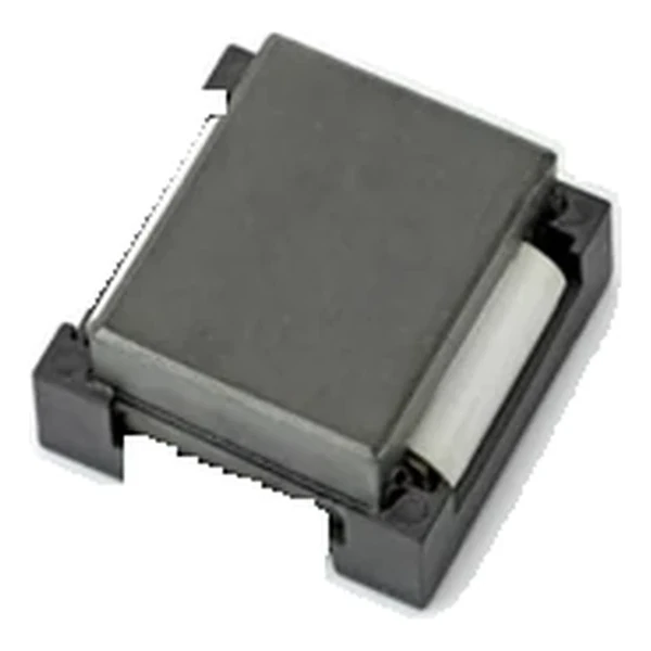
- Core material: ferrite core, 19.2 x 19.2 mm body at 11.18 mm.
- Typical applications: distributed power systems dc-dc converters; general-purpose low voltage supplies; computer systems; servers; point of load (pol) converters; industrial equipment.
- The rated current assumes a 40 °C rise from DC alone. AC ripple raises the winding temperature further, and the derating curves in the data sheet are there for exactly that case.
Sizing It Into a Design
Copper resistance rises with temperature, so at the +125 °C limit the maximum DCR of 4.6 mOhm becomes roughly 6.5 mOhm. That is the figure to put into a hot-enclosure loss calculation; the +20 °C column is a bench number.
Design note: on a low-voltage rail the DCR drop is a real fraction of the output. Compare the millivolt drop at rated current against the converter tolerance before choosing the smallest inductance in the family.
- Apply the AC derating curve before assuming the 40 °C rise figure holds.
- Leave clearance for the tape-and-reel orientation if the line places by vision.
- Confirm the pad layout against the drawing: the terminal geometry sets the solder fillet and therefore the thermal path.
Frequently Asked Questions
Can this replace a powdered-core part of the same value?
Only if the saturation behaviour is acceptable. Ferrite saturates abruptly compared with a powder core, so the transient margin has to be re-checked even when the inductance and DCR look similar.
What does the DCR tolerance mean for paralleling?
Parts are not matched for DCR, so two in parallel will not share current exactly. The mismatch is set by the DCR tolerance, and because the DCR is only fractions of a milliohm, a small absolute difference is a large percentage one.
Is the part suitable for a SEPIC or buck-boost stage?
The inductance and current ratings suit it, but check the AC flux swing: in a buck-boost the inductor carries the full input current continuously, so the core loss is higher than in a buck stage of the same output.
Shenzhen Gaorunxin Technology Co., Ltd
Online message
Shenzhen Gaorunxin Technology Co., Ltd