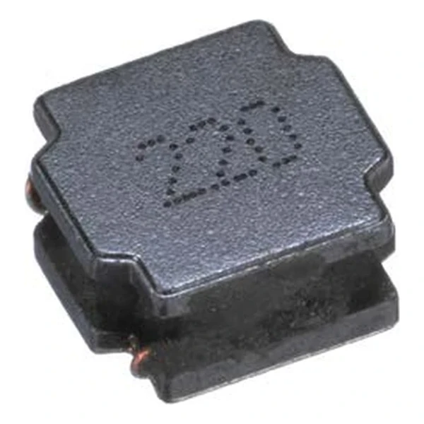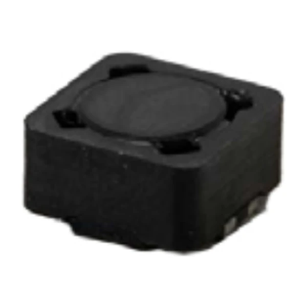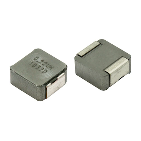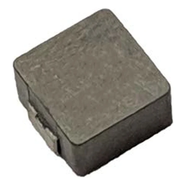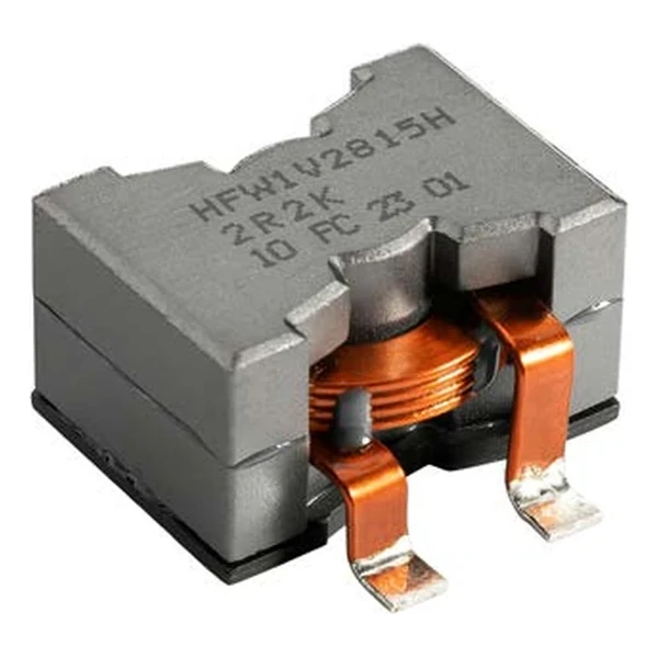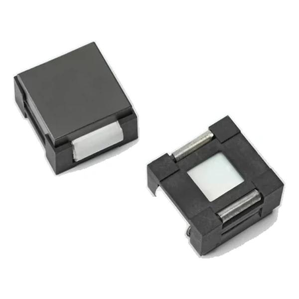
Eaton HC3-R50-R 0.50 uH High-Current Inductor 0.42 mOhm
- Product Details
- Download
Eaton HC3-R50-R 0.50 uH High-Current Inductor 0.42 mOhm
Key Specifications
| Parameter | Value |
|---|---|
| Orderable part number | HC3-R50-R |
| OCL (open circuit inductance) | 0.50 uH ±20% |
| Irms (DC, 40 °C rise) | 78 A |
| Isat (20% rolloff @ +25 °C) | 120 A |
| DCR typical @ +20 °C | 0.42 mOhm |
| Volt-time rating (V-us) | 17.3 |
| Package | 30.0 x 25.3 mm |
| Height | 18.0 mm |
| Mounting | Surface mount |
| Operating temperature | -40 °C to +125 °C (ambient plus self-heating) |
| Qualification | Commercial grade |
| RoHS | Compliant, -R suffix |
| Data sheet | Eaton Technical Data 4122 |
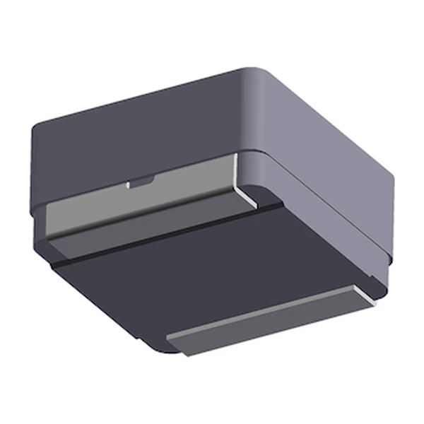
Mechanical Drawing

Drawing reproduced from Eaton Technical Data 4122: outline with
rated mm dimensions, recommended pad layout and winding schematic. Tolerances are stated on
the drawing itself.
Reading the Data Sheet
This part belongs to the HC foil family, built for high-current, low-voltage converters where efficiency is dominated by the copper. Ferrite keeps core loss low at the switching frequency; the foil winding keeps the copper loss low at the DC component. Both halves of the loss budget are addressed in the same body.
At the rated 78 A the winding dissipates about 2.56 W in copper alone, using the typical DCR of 0.42 mOhm. That figure is the floor of the loss budget: it assumes the current is pure DC, and any ripple adds to it.
The Isat column is 20% rolloff @ +25 °C. Note what it does and does not mean: it is a defined rolloff point, not a destruction limit. Above it the inductance continues to fall, which is why the transient peak current should be checked against the curve, not just against the number.
Stored energy at Isat is about 3,600 uJ, which is the energy the inductor hands to the load during a transient before the control loop reacts.
What This Family Is For
The HC foil family covers the low-inductance, very-high-current end of the range: sub-microhenry to a few microhenry, with DC resistance measured in fractions of a milliohm. It is the family to reach for when the rail is a volt or two and the current is tens of amps.
Within the HC3 family this is value 1 of 7, in a range that runs from 0.5 uH to 6.52 uH.
One step down the table, HC3-1R0-R, sits at 1.05 uH with 78 A and 0.42 mOhm – the lower inductance buys about 0 A of extra current in the same body.
- Core material: ferrite core, 30.0 x 25.3 mm body at 18.0 mm.
- Typical applications: distributed power systems dc-dc converters; general-purpose low voltage supplies; computer systems; servers; point of load (pol) converters; industrial equipment.
- The rated current assumes a 40 °C rise from DC alone. AC ripple raises the winding temperature further, and the derating curves in the data sheet are there for exactly that case.
Sizing It Into a Design
Copper resistance rises with temperature, so at the +125 °C limit the maximum DCR of 0.42 mOhm becomes roughly 0.593 mOhm. That is the figure to put into a hot-enclosure loss calculation; the +20 °C column is a bench number.
Design note: on a low-voltage rail the DCR drop is a real fraction of the output. Compare the millivolt drop at rated current against the converter tolerance before choosing the smallest inductance in the family.
- Apply the AC derating curve before assuming the 40 °C rise figure holds.
- Confirm the pad layout against the drawing: the terminal geometry sets the solder fillet and therefore the thermal path.
- At frequencies above a few hundred kilohertz, check the AC resistance rise before assuming the DC figure holds.
Frequently Asked Questions
What does the DCR tolerance mean for paralleling?
Parts are not matched for DCR, so two in parallel will not share current exactly. The mismatch is set by the DCR tolerance, and because the DCR is only fractions of a milliohm, a small absolute difference is a large percentage one.
Why foil instead of round wire?
At high frequency the current crowds into the surface of the conductor. A flat foil presents a wide surface for the same cross-section, so the AC resistance stays closer to the DC value and the winding runs cooler.
What does the DCR tolerance mean for paralleling?
Parts are not matched for DCR, so two in parallel will not share current exactly. The mismatch is set by the DCR tolerance, and because the DCR is only fractions of a milliohm, a small absolute difference is a large percentage one.
Shenzhen Gaorunxin Technology Co., Ltd
Online message
Shenzhen Gaorunxin Technology Co., Ltd