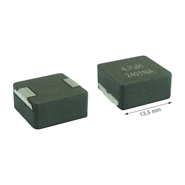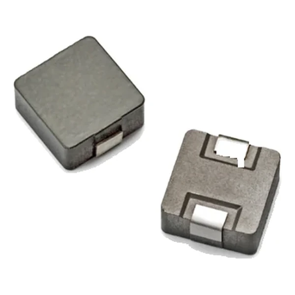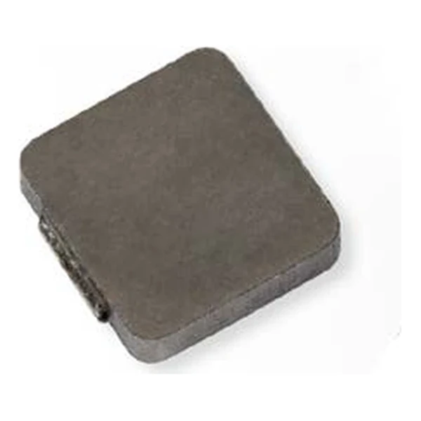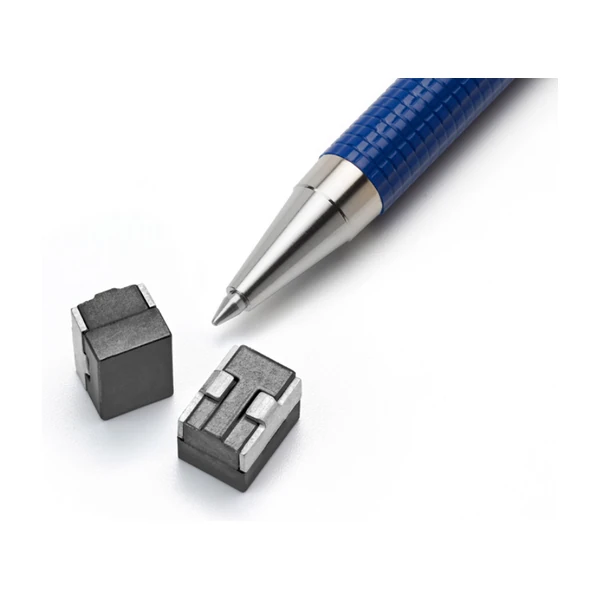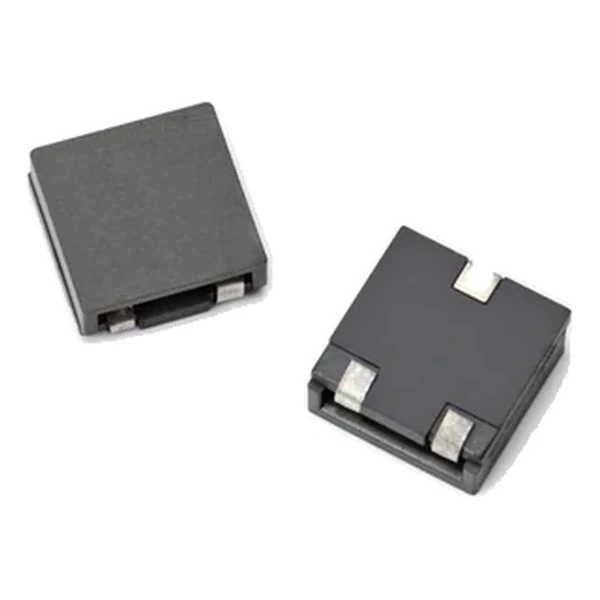
Eaton HCF1305-2R2-R Ferrite Inductor 2.20 uH, Isat 15 A
- Product Details
- Download
Eaton HCF1305-2R2-R Ferrite Inductor 2.20 uH, Isat 15 A
Ratings at a Glance
| Parameter | Value |
|---|---|
| Orderable part number | HCF1305-2R2-R |
| Rated inductance | 2.2 uH ±20% |
| OCL (open circuit inductance) | 2.20 uH ±20% |
| Irms (DC, 40 °C rise) | 16.3 A |
| Isat (30% rolloff @ +25 °C) | 15 A |
| Isat2 (30% rolloff @ +125 °C) | 11.2 A |
| DCR typical @ +20 °C | 2.58 mOhm |
| DCR maximum @ +20 °C | 3.1 mOhm |
| K-factor (Bp-p = K x L x dI) | 10, Bp-p in mT |
| Package | 12.5 x 12.5 mm |
| Height | 5.0 mm |
| Mounting | Surface mount |
| Operating temperature | -40 °C to +125 °C (ambient plus self-heating) |
| Qualification | Commercial grade |
| RoHS | Compliant, -R suffix |
| Data sheet | Eaton Technical Data 4133 |
Dimensions and Pad Layout

Drawing reproduced from Eaton Technical Data 4133: outline with
rated mm dimensions, recommended pad layout and winding schematic. Tolerances are stated on
the drawing itself.
How to Read These Ratings
Ferrite core, high current, and a winding built to keep the DC resistance low: this family sits between the foil-wound parts and the molded powder parts. Ferrite gives low core loss at the switching frequency; the construction gives a low DCR and a tight tolerance, which matters when the inductor is also the current-sense element.
Copper loss at the rated current works out to roughly 0.685 W from a typical DCR of 2.58 mOhm at 16.3 A. It is the number to start a thermal stack-up with, before core loss and before AC resistance rise.
Isat is specified as 30% rolloff @ +25 °C, so the number is a rolloff criterion rather than an absolute maximum. The useful working range extends a little beyond it on a soft saturation core, but the loop compensation has to be designed for the inductance that remains.
At Isat the part holds about 248 uJ. On a multiphase rail that is the energy per phase available to bridge a load step, which sets how much bulk capacitance the controller still needs.
With K = 10, a peak-to-peak ripple of one amp produces roughly 22 mT of flux swing. Read the core-loss graph at that amplitude and at the switching frequency to get the core contribution to the total loss.
The second saturation column, 11.2 A at 30% rolloff @ +125 °C, is the same core taken further into rolloff. The ratio between the two columns is a direct measure of how soft the curve is: a part with a wide gap between them loses inductance slowly and tolerates a larger transient peak.
Where This Series Fits
The HCF family is the ferrite option in the high-current range: lower core loss than a powder part at high frequency, with saturation current quoted at both +25 °C and +125 °C. It is the family for converters that run fast and hot.
Of the 10 values listed for HCF1305, this is the 6th, in a family covering 0.47 uH to 4.7 uH.
One step down the table, HCF1305-1R8-R, sits at 1.80 uH with 16.3 A and 2.58 mOhm – the lower inductance buys about 3.1 A of extra current in the same body.
- Core material: ferrite core, 12.5 x 12.5 mm body at 5.0 mm.
- Typical applications: voltage regulator modules (vrm); high current dc-dc converters; multi-phase buck regulators; servers and data networking; point-of-load modules.
- Ferrite loses saturation margin as it heats. The +125 °C Isat column is the one that governs a hot design; the +25 °C figure is the optimistic one.
Design Notes
Copper resistance rises with temperature, so at the +125 °C limit the maximum DCR of 3.1 mOhm becomes roughly 4.38 mOhm. That is the figure to put into a hot-enclosure loss calculation; the +20 °C column is a bench number.
Design note: the full-load inductance (FLL) is the value to use for ripple at rated current. OCL is the small-signal number; FLL is what the converter actually sees under load.
- Read the core-loss curve at the Bp-p implied by the K-factor and the ripple.
- Confirm the terminal arrangement matches the pad layout for three-terminal parts.
- Read the core-loss curve at the Bp-p implied by the K-factor and the ripple.
Frequently Asked Questions
What is the difference between OCL and FLL?
OCL is the open-circuit inductance measured at low signal. FLL is the inductance remaining at the saturation current. Ripple at full load should be calculated with FLL, not OCL.
What happens above the self-resonant frequency?
The part becomes capacitive and no longer behaves as an inductor. Keep the switching frequency and the harmonics that carry energy comfortably below SRF where one is quoted.
Is this part suitable for current sensing?
The family includes parts with tight DCR tolerance for exactly that purpose, but the tolerance is quoted at +20 °C. Copper drift with temperature has to be compensated in the sensing circuit.
Shenzhen Gaorunxin Technology Co., Ltd
Online message
Shenzhen Gaorunxin Technology Co., Ltd