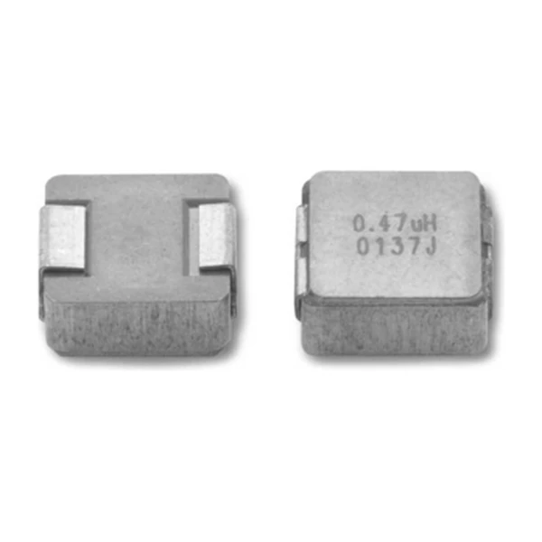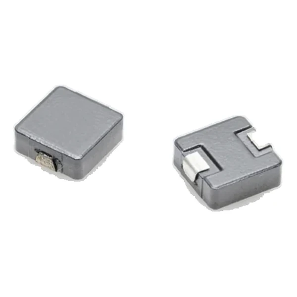
Eaton HCM1305-100-R Molded Inductor 10.0 uH, Isat 16 A
- Product Details
- Download
Eaton HCM1305-100-R Molded Inductor 10.0 uH, Isat 16 A
Specification Table
| Parameter | Value |
|---|---|
| Orderable part number | HCM1305-100-R |
| OCL (open circuit inductance) | 10.0 uH ±20% |
| FLL minimum, at Isat | 6.4 uH |
| Irms (DC, 40 °C rise) | 9 A |
| Isat (20% rolloff @ +25 °C) | 16 A |
| DCR typical @ +20 °C | 19 mOhm |
| DCR maximum @ +20 °C | 21.9 mOhm |
| K-factor (Bp-p = K x L x dI) | 90, Bp-p in Gauss |
| Package | 13.8 x 12.5 mm |
| Height | 5.0 mm |
| Mounting | Surface mount |
| Operating temperature | -55 °C to +125 °C (ambient plus self-heating) |
| Qualification | Commercial grade |
| RoHS | Compliant, -R suffix |
| Data sheet | Eaton Technical Data 4371 |
Mechanical Drawing

Drawing reproduced from Eaton Technical Data 4371: outline with
rated mm dimensions, recommended pad layout and winding schematic. Tolerances are stated on
the drawing itself.
How to Read These Ratings
Molded construction is what gives this family its mechanical robustness and its shielding. Because the core surrounds the winding on all sides, the leakage field that would otherwise couple into adjacent traces is small, and the part can be placed close to sensitive nodes.
Copper loss at the rated current works out to roughly 1.54 W from a typical DCR of 19 mOhm at 9 A. It is the number to start a thermal stack-up with, before core loss and before AC resistance rise.
Saturation is quoted as 20% rolloff @ +25 °C. At that point the inductance has fallen to the stated fraction of its nominal value – the part is not damaged there, it simply stops behaving like the inductance on the label. Design the peak current to stay inside that boundary with margin for tolerance.
Stored energy at Isat is about 1,280 uJ, which is the energy the inductor hands to the load during a transient before the control loop reacts.
With K = 90, a peak-to-peak ripple of one amp produces roughly 900 Gauss of flux swing. Read the core-loss graph at that amplitude and at the switching frequency to get the core contribution to the total loss.
Where This Series Fits
The HCM family is the commercial molded range: shielded powder-core parts from a 5.5 mm footprint up to a 17.5 mm body, covering 0.1 uH to tens of microhenry at currents from a few amps to over a hundred.
The HCM1305 family spans 0.1 uH to 33 uH; this row sits at position 18 of 21.
One step down the table, HCM1305-8R2-R, sits at 8.20 uH with 9.5 A and 17.5 mOhm – the lower inductance buys about 1.8 A of extra current in the same body.
- Core material: iron powder core, 13.8 x 12.5 mm body at 5.0 mm.
- Typical applications: voltage regulator module (vrm); multi-phase regulators; point-of-load modules; desktop and server vrms and evrds; base station equipment; notebook and laptop regulators.
- The DCR columns are typical and maximum at +20 °C. Copper rises about 0.4 % per °C, so the hot resistance is higher than either column suggests.
Sizing It Into a Design
Copper resistance rises with temperature, so at the +125 °C limit the maximum DCR of 21.9 mOhm becomes roughly 30.9 mOhm. That is the figure to put into a hot-enclosure loss calculation; the +20 °C column is a bench number.
Design note: two DCR columns let the loss budget be built either on the typical part or on the worst-case part. Use maximum for a guaranteed thermal design, typical for a nominal one.
- Verify the body height against the enclosure or heat-spreader clearance.
- Confirm the peak transient current stays under Isat with tolerance margin.
- Build the thermal design on the maximum DCR, not the typical one.
Frequently Asked Questions
Is it magnetically shielded?
Yes. The powder core surrounds the winding, so the leakage field is small and the part can sit close to sensitive traces without a shield can.
Why quote typical and maximum DCR?
A guaranteed thermal design uses the maximum. A nominal efficiency calculation uses the typical. Publishing both lets the same table serve either purpose.
Why quote typical and maximum DCR?
A guaranteed thermal design uses the maximum. A nominal efficiency calculation uses the typical. Publishing both lets the same table serve either purpose.
Shenzhen Gaorunxin Technology Co., Ltd
Online message
Shenzhen Gaorunxin Technology Co., Ltd