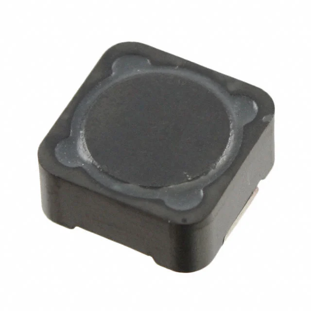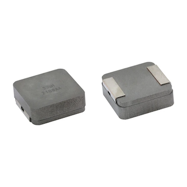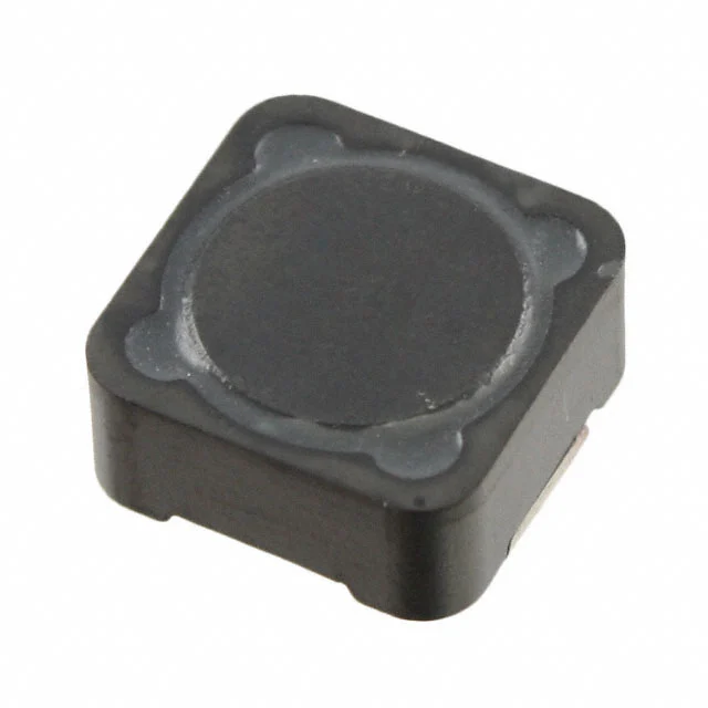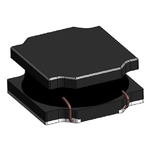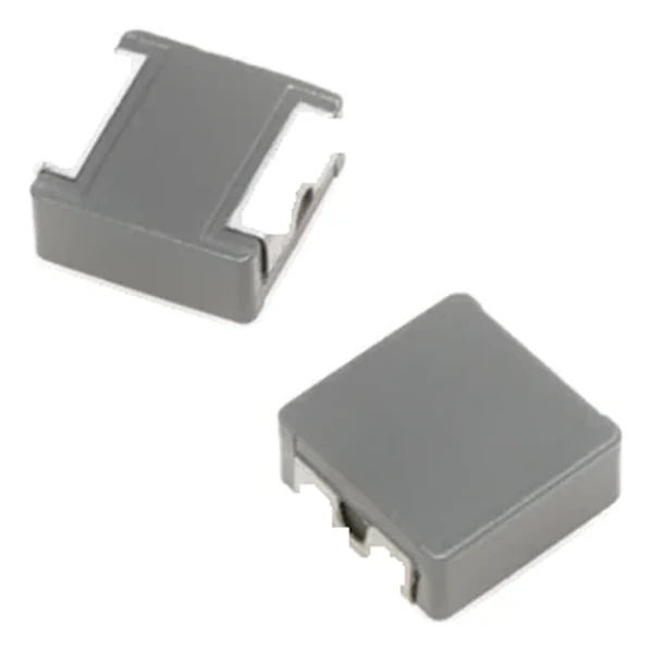
Eaton HCM1707-8R2-R 8.2 uH High-Current Inductor 8.1 mOhm
- Product Details
- Download
Eaton HCM1707-8R2-R 8.2 uH High-Current Inductor 8.1 mOhm
Specification Table
| Parameter | Value |
|---|---|
| Orderable part number | HCM1707-8R2-R |
| OCL (open circuit inductance) | 8.2 uH ±20% |
| FLL minimum, at Isat | 5.25 uH |
| Irms (DC, 40 °C rise) | 16 A |
| Isat (20% rolloff @ +25 °C) | 20 A |
| DCR typical @ +20 °C | 8.1 mOhm |
| DCR maximum @ +20 °C | 8.7 mOhm |
| K-factor (Bp-p = K x L x dI) | 55, Bp-p in Gauss |
| Package | 17.5 x 17.2 mm |
| Height | 7.0 mm |
| Mounting | Surface mount |
| Operating temperature | -40 °C to +125 °C (ambient plus self-heating) |
| Qualification | Commercial grade |
| RoHS | Compliant, -R suffix |
| Data sheet | Eaton Technical Data 10295 |
Mechanical Drawing

Drawing reproduced from Eaton Technical Data 10295: outline with
rated mm dimensions, recommended pad layout and winding schematic. Tolerances are stated on
the drawing itself.
The Figures Explained
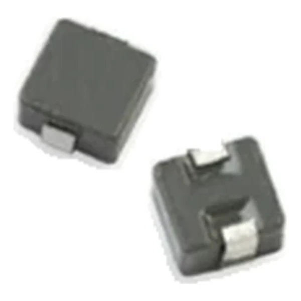
The part is a surface-mount molded inductor: powder core, directly wound and pressed, with the terminals formed from the winding ends. The absence of a bobbin or an air gap in the magnetic path is what keeps the DCR low for the current rating, and the soft saturation is a property of the distributed gap.
Copper loss at the rated current works out to roughly 2.07 W from a typical DCR of 8.1 mOhm at 16 A. It is the number to start a thermal stack-up with, before core loss and before AC resistance rise.
The saturation rating reads 20% rolloff @ +25 °C. Treat it as the edge of the linear region: below it the inductance is within tolerance, above it the value droops. For a current-mode converter that means the peak current at the worst-case load step is what must fit under this number.
The core stores roughly 1,640 uJ at the saturation point – a useful figure when sizing the output capacitance that has to absorb the same transient.
K-factor 55 means the flux swing is about 451 Gauss per amp of ripple. Core loss scales with the flux amplitude and the frequency, so this is the number to carry into the loss calculation rather than the inductance alone.
What This Family Is For
The HCM family is the commercial molded range: shielded powder-core parts from a 5.5 mm footprint up to a 17.5 mm body, covering 0.1 uH to tens of microhenry at currents from a few amps to over a hundred.
Within the HCM1707 family this is value 5 of 11, in a range that runs from 1.5 uH to 68 uH.
Compared with its neighbours in the table, HCM1707-100-R trades 6 A of rated current for the next inductance step, which is the usual compromise in this family.
- Core material: iron powder core, 17.5 x 17.2 mm body at 7.0 mm.
- Typical applications: voltage regulator module (vrm); multi-phase regulators; point-of-load modules; desktop and server vrms and evrds; data networking and storage systems; base station equipment.
- The DCR columns are typical and maximum at +20 °C. Copper rises about 0.4 % per °C, so the hot resistance is higher than either column suggests.
Sizing and Layout Notes
Copper resistance rises with temperature, so at the +125 °C limit the maximum DCR of 8.7 mOhm becomes roughly 12.3 mOhm. That is the figure to put into a hot-enclosure loss calculation; the +20 °C column is a bench number.
Design note: two DCR columns let the loss budget be built either on the typical part or on the worst-case part. Use maximum for a guaranteed thermal design, typical for a nominal one.
- Confirm the shielding is adequate for the adjacent trace routing.
- Verify the body height against the enclosure or heat-spreader clearance.
- Build the thermal design on the maximum DCR, not the typical one.
Frequently Asked Questions
Is it magnetically shielded?
Yes. The powder core surrounds the winding, so the leakage field is small and the part can sit close to sensitive traces without a shield can.
What makes a molded inductor different?
The winding is pressed into the magnetic powder with no bobbin or air gap in the path. That is why the body is almost all magnetic material, the DCR is low for the size, and the part is mechanically robust.
How much does the inductance drop at rated current?
That is what the Isat column quantifies. At the rated DC current the part is still inside the rolloff boundary, but the ripple calculation should use the FLL column rather than OCL.
Shenzhen Gaorunxin Technology Co., Ltd
Online message
Shenzhen Gaorunxin Technology Co., Ltd