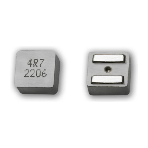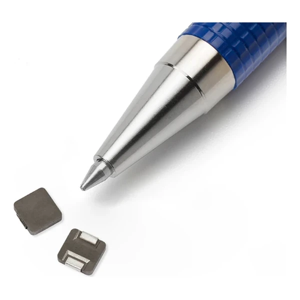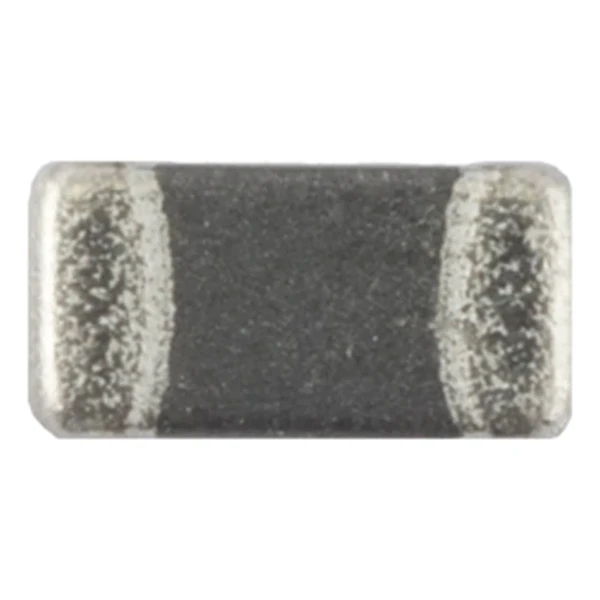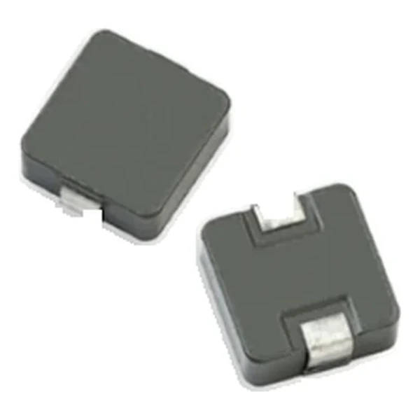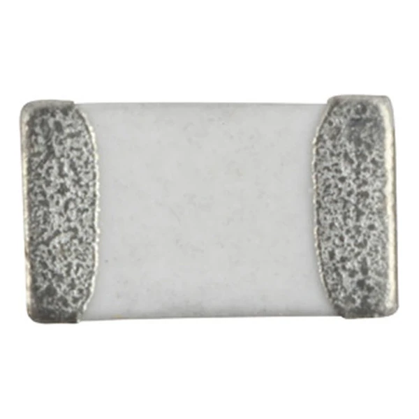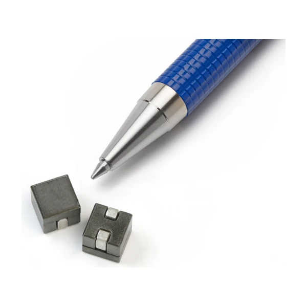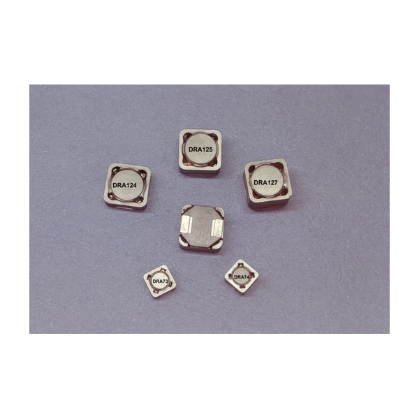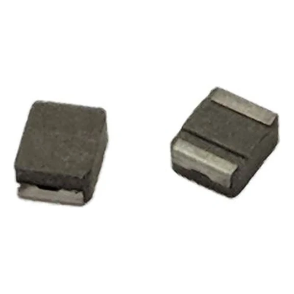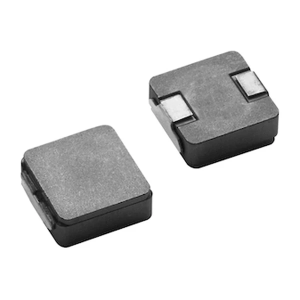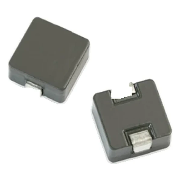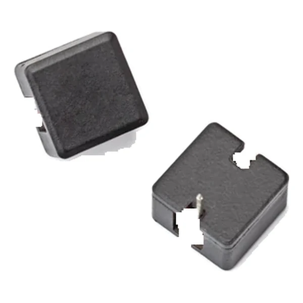
Eaton HCPT1309-3R3-R 3.31 uH Vertical Power Inductor
- Product Details
- Download
Eaton HCPT1309-3R3-R 3.31 uH Vertical Power Inductor
Specification Table
| Parameter | Value |
|---|---|
| Orderable part number | HCPT1309-3R3-R |
| OCL (open circuit inductance) | 3.31 uH ±20% |
| Irms (DC, 40 °C rise) | 11.4 A |
| Isat (20% rolloff @ +20 °C) | 16.7 A |
| Isat2 (30% rolloff @ +20 °C) | 21 A |
| DCR typical @ +20 °C | 4.8 mOhm |
| K-factor (Bp-p = K x L x dI) | 35.6, Bp-p in Gauss |
| Package | 13.2 x 13.2 mm |
| Height | 9.0 mm |
| Mounting | Through-hole, vertical |
| Operating temperature | -40 °C to +105 °C (ambient plus self-heating) |
| Qualification | Commercial grade |
| RoHS | Compliant, -R suffix |
| Data sheet | Eaton Technical Data 4138 |
Dimensions and Pad Layout

Drawing reproduced from Eaton Technical Data 4138: outline with
rated mm dimensions, recommended pad layout and winding schematic. Tolerances are stated on
the drawing itself.
Reading the Data Sheet
This is a vertical through-hole inductor for high-current DC-DC stages. Powder core, two saturation columns (20% and 30% rolloff), and a DCR in the fractions of a milliohm: the part is built for the main output inductor of a multiphase regulator on a board that still uses wave or selective soldering.
The DCR figure of 4.8 mOhm is what sets the efficiency: at 11.4 A the winding drops about 0.055 mV and dissipates 0.624 W. On a low-voltage rail that drop is a measurable fraction of the output, so the DCR column deserves as much attention as the inductance.
Saturation is quoted as 20% rolloff @ +20 °C. At that point the inductance has fallen to the stated fraction of its nominal value – the part is not damaged there, it simply stops behaving like the inductance on the label. Design the peak current to stay inside that boundary with margin for tolerance.
At Isat the part holds about 462 uJ. On a multiphase rail that is the energy per phase available to bridge a load step, which sets how much bulk capacitance the controller still needs.
With K = 35.6, a peak-to-peak ripple of one amp produces roughly 118 Gauss of flux swing. Read the core-loss graph at that amplitude and at the switching frequency to get the core contribution to the total loss.
The second saturation column, 21 A at 30% rolloff @ +20 °C, is the same core taken further into rolloff. The ratio between the two columns is a direct measure of how soft the curve is: a part with a wide gap between them loses inductance slowly and tolerates a larger transient peak.
Series Positioning
The HCPT family is the through-hole, vertical-mount high-current range. It exists for boards that need maximum current per square millimetre and are assembled by wave or selective soldering rather than reflow.
In the HCPT1309 line-up this part is number 6 of 6 by inductance, between 0.2 uH and 3.31 uH.
One step down the table, HCPT1309-2R2-R, sits at 2.27 uH with 12.5 A and 4.1 mOhm – the lower inductance buys about 0 A of extra current in the same body.
- Core material: iron powder core, 13.2 x 13.2 mm body at 9.0 mm.
- Typical applications: next generation processors; high current dc-dc converters; vrm, multi-phase buck regulator; desktop computers; video game power.
- Through-hole mounting puts the solder joint in the current path. Check the joint and the plated barrel, not just the lead, against the rated current.
Sizing It Into a Design
Copper resistance rises with temperature, so at the +105 °C limit the maximum DCR of 4.8 mOhm becomes roughly 6.4 mOhm. That is the figure to put into a hot-enclosure loss calculation; the +20 °C column is a bench number.
Design note: the vertical body blocks airflow across the board. If the enclosure relies on lateral airflow, check the thermal path through the leads and the copper around them.
- Check the standing height against the enclosure clearance.
- Verify the solder joint temperature in the thermal test, not the body temperature.
- Provide a thermal path through the leads when lateral airflow is blocked.
Frequently Asked Questions
Does the vertical body affect cooling?
It blocks lateral airflow, so the thermal path is through the leads and the copper around them. Check the joint temperature, not just the body temperature.
What are the two saturation figures?
The same peak current measured at two rolloff criteria – 20 % and 30 % of inductance. They are design boundaries, not damage limits.
Does the vertical body affect cooling?
It blocks lateral airflow, so the thermal path is through the leads and the copper around them. Check the joint temperature, not just the body temperature.
Shenzhen Gaorunxin Technology Co., Ltd
Online message
Shenzhen Gaorunxin Technology Co., Ltd