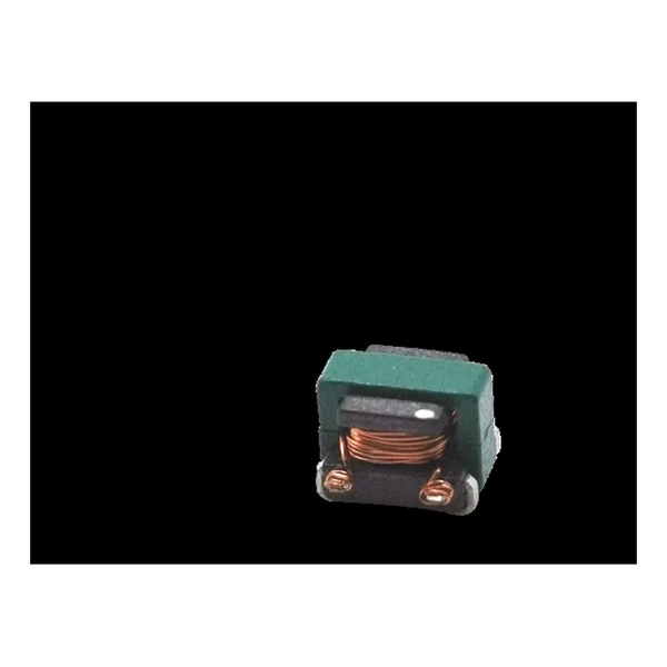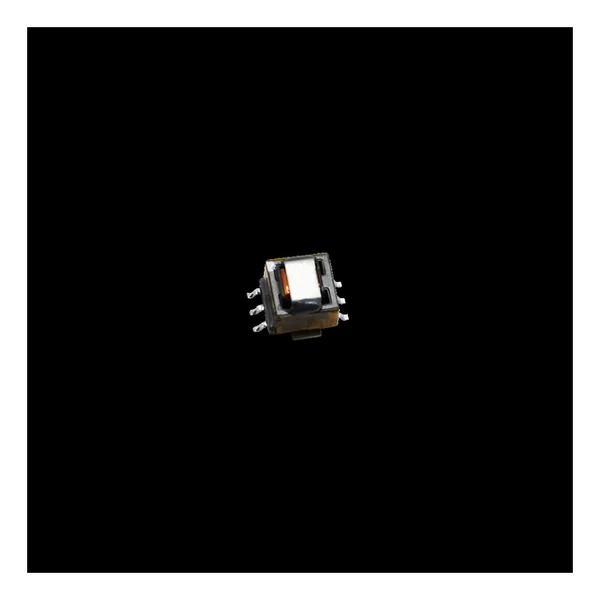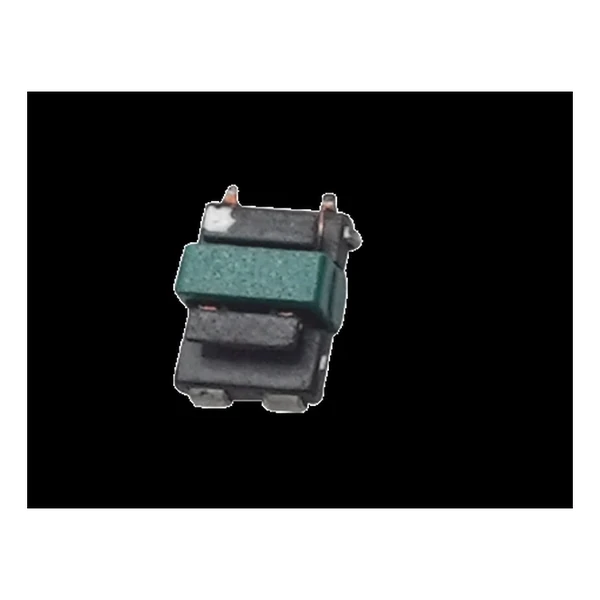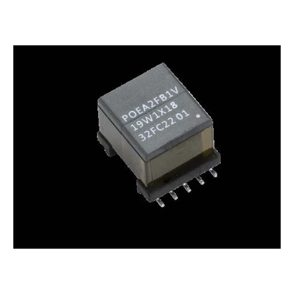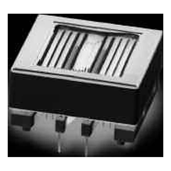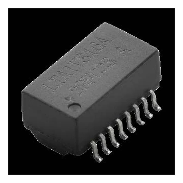
Eaton LTA1VS16B-351-R Ethernet Isolation Transformer
- Product Details
- Download
Eaton LTA1VS16B-351-R Ethernet Isolation Transformer
Key Specifications
| Parameter | Value |
|---|---|
| Orderable part number | LTA1VS16B-351-R |
| Ports | Single |
| Pins | 16 |
| Inductance | 350 uH |
| Leakage inductance | 0.5 uH |
| DCR maximum | 1.2 Ohm |
| Inter-winding capacitance | 35 pF |
| Insertion loss | -1.1 dB @ 1-100 MHz |
| Return loss | -18 dB @ 0.5-30 MHz |
| Package | See dimension drawing in the data sheet |
| Mounting | Surface mount |
| Operating temperature | -40 C to +125 C |
| Qualification | AEC-Q200 |
| RoHS | Compliant, -R suffix |
| Data sheet | Eaton Technical Data ELX1396 |
Outline drawing, winding arrangement and recommended pad layout are on
page 2 of Eaton Technical Data ELX1396; the package line above gives the body size where
the data sheet states it.
The Figures Explained
Ethernet magnetics are specified in the frequency domain, not at DC. Insertion loss and return loss over the band matter more than the inductance number, which is only there to guarantee the low-frequency corner.
Insertion loss of -1.1 dB @ 1-100 MHz is the figure that matters at the band edge; the inductance value only guarantees the low-frequency corner.
Within the LTA1VS16B family this is item 1 of 1 in the Eaton catalogue.
Where This Series Fits
The LAN range covers 100BASE-T through 10GBASE-T, single to quad port, with and without PoE, in open-header SMT packages.
- The magnetics set the return loss and crosstalk floor of the link. A marginal part cannot be fixed in layout.
- Typical applications: t-box; 10base-t/100base-tx interface; infotainment; battery management systems.
- Design note: insertion loss and return loss are band specifications. Compare curves at the band edges, not the typical number.
Frequently Asked Questions
Why is inductance quoted at a DC bias?
The PHY or the PoE feed pushes a DC current through the winding, and the core saturates a little. The bias condition in the table is the one the number applies to; without it the figure is meaningless.
What is CWW?
Inter-winding capacitance. It is the path that lets common mode noise through the transformer, so lower is better for EMC. It is a construction parameter, not something the layout can fix.
Does the part include the common mode choke?
Only where the part number or the description says so. Many designs use a separate choke; the PoE variants with a CMC in the same package are marked as such.
Shenzhen Gaorunxin Technology Co., Ltd
Online message
Shenzhen Gaorunxin Technology Co., Ltd