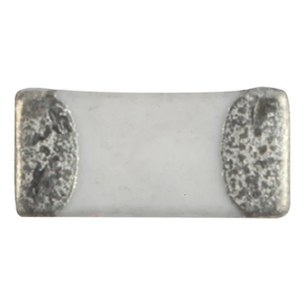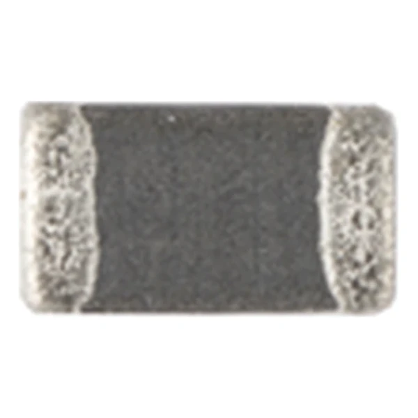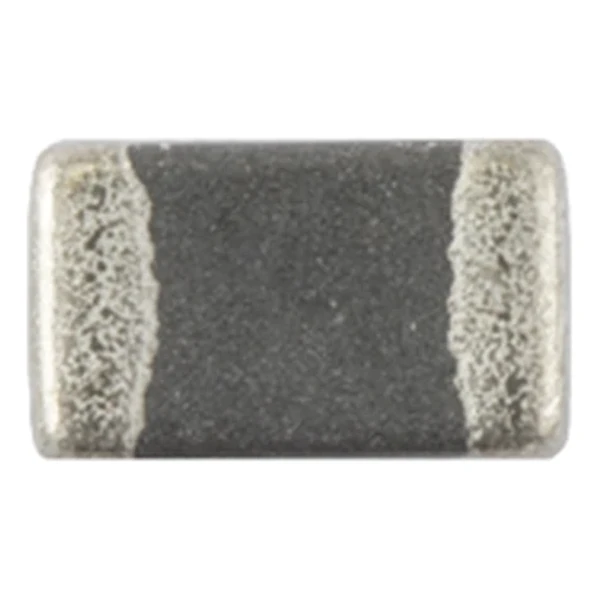
Eaton MFBA2V2012-301-R 300 Ohm Multilayer Chip Bead
- Product Details
- Download
Eaton MFBA2V2012-301-R 300 Ohm Multilayer Chip Bead
Electrical Specifications
| Parameter | Value |
|---|---|
| Orderable part number | MFBA2V2012-301-R |
| Impedance @ 100 MHz | 300 Ohm |
| DCR maximum @ +25 °C | 200 mOhm |
| Rated current maximum | 1000 mA |
| Package | 2.0 x 1.25 mm |
| Size code | 2012 (0805) |
| Mounting | Surface mount |
| Operating temperature | -55 °C to +150 °C |
| Qualification | AEC-Q200 |
| RoHS | Compliant, -R suffix |
| Data sheet | Eaton Technical Data ELX1132 |
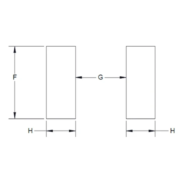
Dimensions and Pad Layout

Drawing reproduced from Eaton Technical Data ELX1132: outline with rated mm dimensions, pad layout and marking. Tolerances are stated on the drawing.
Reading the Data Sheet
Beads are placed in series with a supply or signal line to take the high-frequency edge off it. The rated current and the DCR decide whether the part can sit in a power path; the impedance decides how much noise it removes.
At 100 MHz this bead presents 300 ohm, and its DC resistance is 200 mOhm maximum. At the rated 1000 mA that resistance drops 0.2 V, which is the figure to check against the rail tolerance.
Within the MFBA2V2012 family this is value 6 of 9, in a range that runs from 0 to 0 nH.
Series Positioning
The ferrite bead family spans a few ohms to several hundred ohms at 100 MHz, in 0201 through 1206 bodies. Current ratings run from a few hundred milliamps in the small sizes to several amps in the larger ones.
- A bead in a power path drops DC volts according to its DCR. Check that drop against the rail tolerance before choosing a high-impedance part.
- Typical applications: body electronics (keyless entry, ecu, antennas); advanced driver assistance systems (adas); infotainment and cluster electronics; safety electronics systems; wlan, wifi, bluetooth.
- Design note: pick the bead from the impedance curve at the failing frequency, then check the DC current and DCR for the line it sits in.
Frequently Asked Questions
What does the impedance tolerance mean?
It is the allowed spread around the nominal impedance. Low-value beads are specified as a range, for example 0 to 15 ohm, because a percentage tolerance at those values would be meaningless.
How do I choose between MFBM and MFBW?
MFBM is the high-current series: lower impedance per size, higher rated current. MFBW is the high-impedance series for signal lines where DC current is small.
How do I choose between MFBM and MFBW?
MFBM is the high-current series: lower impedance per size, higher rated current. MFBW is the high-impedance series for signal lines where DC current is small.
Shenzhen Gaorunxin Technology Co., Ltd
Online message
Shenzhen Gaorunxin Technology Co., Ltd