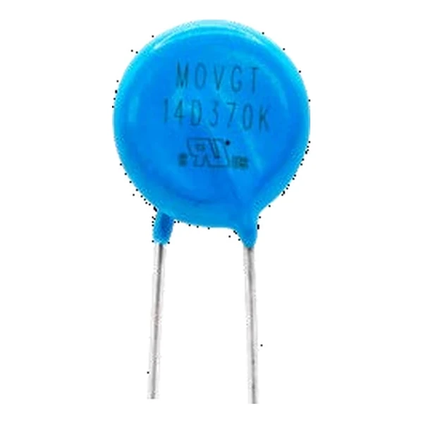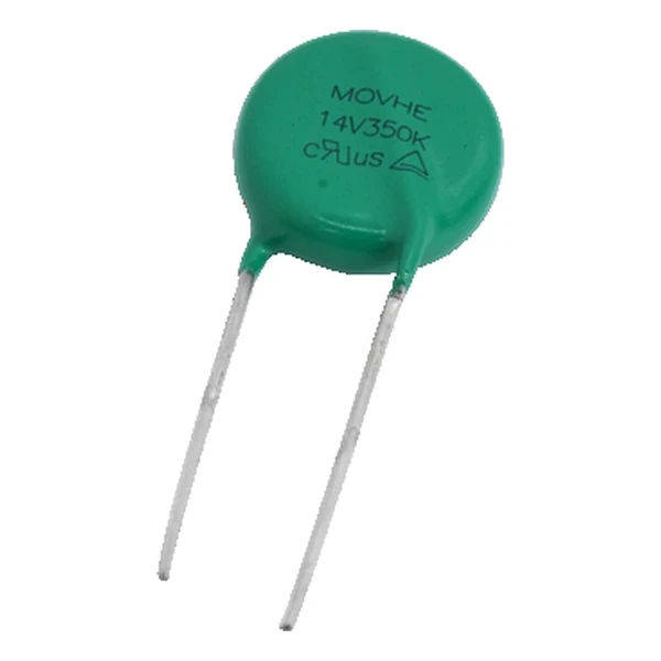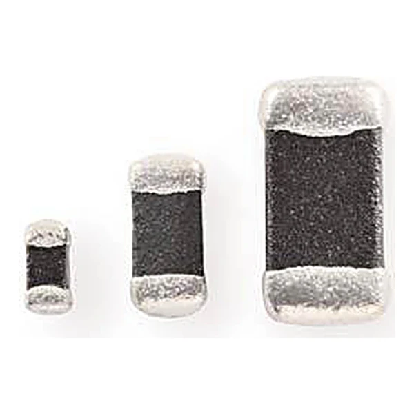
Eaton MLVA02V05C064-R 0201 Chip Varistor 5.5 Vdc
- Product Details
- Download
Eaton MLVA02V05C064-R 0201 Chip Varistor 5.5 Vdc
Ratings at a Glance
| Parameter | Value |
|---|---|
| Orderable part number | MLVA02V05C064-R |
| Package size | 0201 |
| Working voltage, DC | 5.5 Vdc |
| Varistor voltage at 1 mA | 8-14 V |
| Clamping voltage | 26 V |
| Typical capacitance | 64 pF |
| Package | 0201 (0603 metric) |
| Mounting | Surface mount |
| Operating temperature | -40 °C to +85 °C |
| Qualification | Commercial grade |
| RoHS | Compliant, halogen free |
| Data sheet | Eaton Technical Data 10493 |
Dimensions, recommended pad or hole pattern and the derating curves are
on the data sheet pages; the package line above gives the body size as Eaton states it.
Reading the Data Sheet
A chip varistor is a ceramic body with two metal terminations, so it looks like a capacitor and behaves like one until the transient arrives. That is why the capacitance column is quoted on every page: it is the parameter that decides whether the part can sit on a data line.
The clamp column works out at 3.25 times the varistor voltage: 26 V at the rated current against 8-14 V at 1 mA. That ratio is what the downstream part has to survive, not the 8-14 V figure on the label.
The 64 pF typical capacitance is the cost of the clamp. On a power rail it is irrelevant; on a data line it is the reason to look at the low-capacitance versions of the same voltage.
Within the MLVA-R family this is item 3 of 10 in the Eaton catalogue.
Where This Series Fits
The return path is half the component. A varistor tied to a ground plane far from the connector leaves the loop inductance in series with the clamp, and the residual voltage at the chip is the clamp plus L di/dt.
- The energy rating assumes a single pulse. Repeating the same transient heats the body faster than the datasheet curve suggests, because the curve is drawn for one event at a time.
- The response time is quoted below a nanosecond because the ceramic turns conductive in the grain boundaries, not because of a junction.
Frequently Asked Questions
Can it protect a differential pair?
Only with a low-capacitance part and a layout that keeps both lines symmetric. A single varistor from each line to ground is normal; one across the pair is not, because it unbalances the pair.
What happens if the part is run above its working voltage?
Leakage rises steeply and the body heats. A varistor is not a clamp with a sharp knee, so continuous operation above the rating is a slow degradation, not an immediate failure.
Does the package size change the electrical ratings?
Yes, the energy and peak current scale with the body volume, so a 0402 and a 1206 of the same voltage are not interchangeable on a surge.
Shenzhen Gaorunxin Technology Co., Ltd
Online message
Shenzhen Gaorunxin Technology Co., Ltd