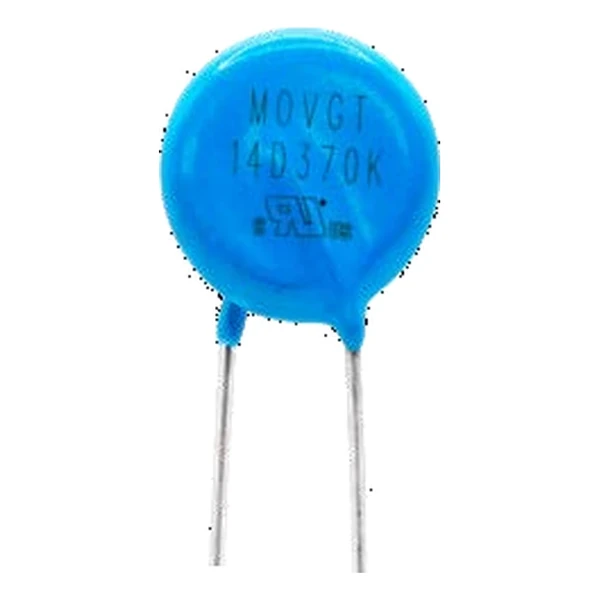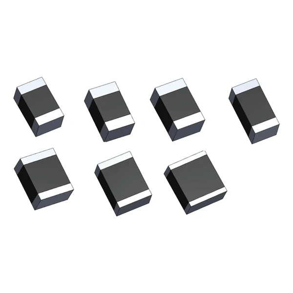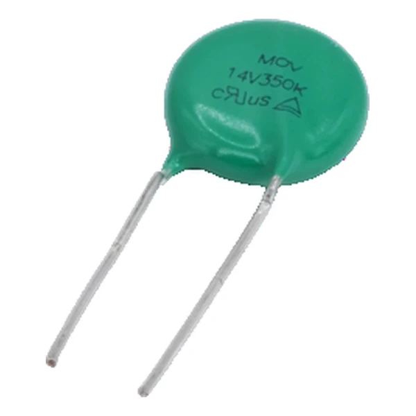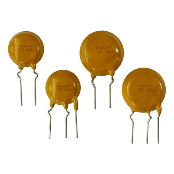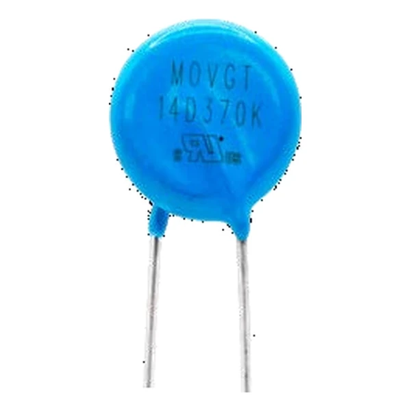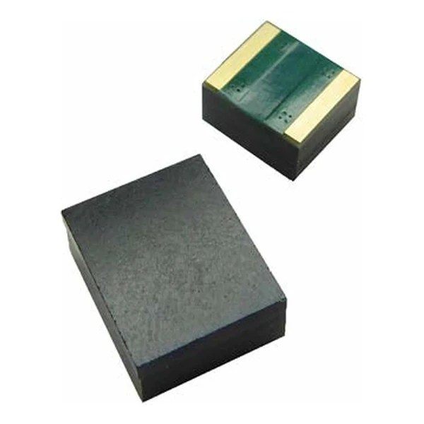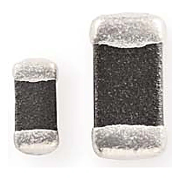
Eaton MLVB06V18C0R5 0603 Chip Varistor 18 Vdc
- Product Details
- Download
Eaton MLVB06V18C0R5 0603 Chip Varistor 18 Vdc
Electrical Specifications
| Parameter | Value |
|---|---|
| Orderable part number | MLVB06V18C0R5 |
| Package size | 0603 |
| Working voltage, DC | 18 Vdc |
| Varistor voltage at 1 mA | 90-120 V |
| Clamping voltage | 250 V |
| Typical capacitance | 0.5 pF |
| Leakage current | max. 10 uA |
| Package | 0603 (1608 metric) |
| Mounting | Surface mount |
| Qualification | Commercial grade |
| RoHS | Compliant, halogen free |
| Data sheet | Eaton Technical Data 4071 |
Dimensions, recommended pad or hole pattern and the derating curves are
on the data sheet pages; the package line above gives the body size as Eaton states it.
How to Read These Ratings
The working voltage is the DC or AC level the part can sit at continuously without conducting appreciably. Pick it above the highest steady-state rail voltage including tolerance, and let the clamp column decide whether the downstream part survives the surge.
The clamp column works out at 2.78 times the varistor voltage: 250 V at the rated current against 90-120 V at 1 mA. That ratio is what the downstream part has to survive, not the 90-120 V figure on the label.
Standing at 18 V the leakage is at most 10 uA, which is 0.18 mW of continuous dissipation. Small, but it is why a varistor on a battery rail has to be chosen on leakage and not only on voltage.
The 0.5 pF typical capacitance is the cost of the clamp. On a power rail it is irrelevant; on a data line it is the reason to look at the low-capacitance versions of the same voltage.
Within the MLVB family this is item 8 of 8 in the Eaton catalogue.
Where This Series Fits
The return path is half the component. A varistor tied to a ground plane far from the connector leaves the loop inductance in series with the clamp, and the residual voltage at the chip is the clamp plus L di/dt.
- The energy rating assumes a single pulse. Repeating the same transient heats the body faster than the datasheet curve suggests, because the curve is drawn for one event at a time.
- The response time is quoted below a nanosecond because the ceramic turns conductive in the grain boundaries, not because of a junction.
Frequently Asked Questions
How many ESD strikes can it take?
The ESD rating is a qualification level, not a lifetime count. IEC 61000-4-2 level 4 is 8 kV contact and 15 kV air, and the part is expected to survive repeated strikes at that level because the energy per strike is small.
Does the clamp voltage scale with the surge current?
Yes. The clamp column is quoted at a stated current, usually 1 A. At ten times that current the residual voltage is higher, so read the V-I curve rather than the single number when the surge is large.
Why is the DC rating lower than the AC rating on some parts?
It is not, on these: the AC rating is an RMS value, so the DC rating is set at the peak of that sine plus margin. Where the two look inconsistent, check which one is quoted as RMS.
Shenzhen Gaorunxin Technology Co., Ltd
Online message
Shenzhen Gaorunxin Technology Co., Ltd