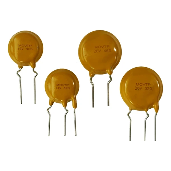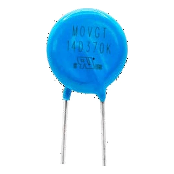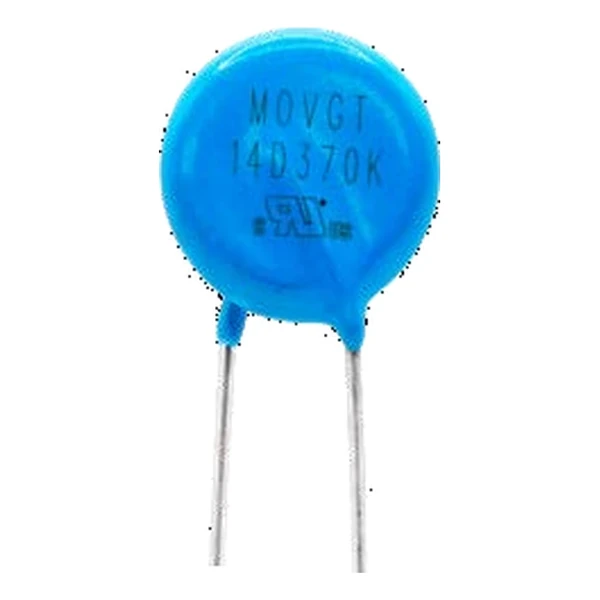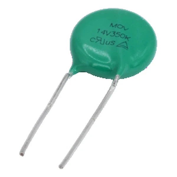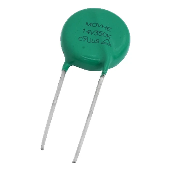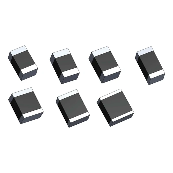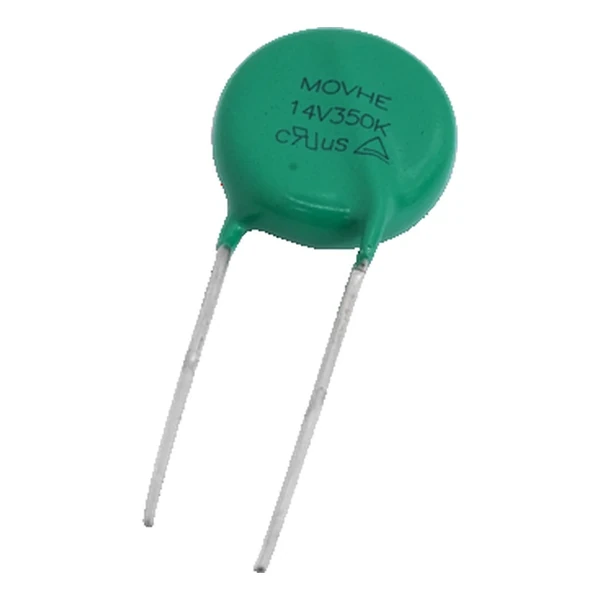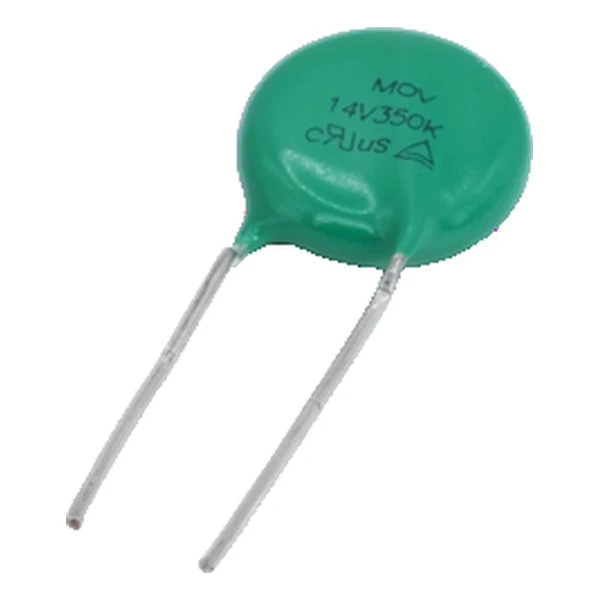
Eaton MOV14V550 Metal Oxide Varistor 910 V
- Product Details
- Download
Eaton MOV14V550 Metal Oxide Varistor 910 V
Ratings at a Glance
| Parameter | Value |
|---|---|
| Orderable part number | MOV14V550 |
| Varistor voltage at 1 mA | 910 V |
| Maximum continuous AC voltage | 550 Vrms |
| Maximum continuous DC voltage | 745 Vdc |
| Clamping voltage | 1500 V |
| Clamping current | 50 A |
| Maximum surge current, 8/20 us | 4500 A |
| Rated power | 0.6 W |
| Typical capacitance at 1 kHz | 220 pF |
| Maximum energy, 10/1000 us | 175 J |
| Maximum body diameter | 7.5 mm |
| Agency recognition | cURus (UL 1449) and TUV |
| Package | 14 mm disc |
| Mounting | Radial, through-hole |
| Operating temperature | -40 °C to +125 °C |
| Qualification | Commercial grade |
| RoHS | Compliant, halogen free |
| Data sheet | Eaton Technical Data ELX1287 |
Dimensions, recommended pad or hole pattern and the derating curves are
on the data sheet pages; the package line above gives the body size as Eaton states it.
How to Read These Ratings
For AC mains service the continuous rating is given as an RMS voltage, and the DC rating is that value multiplied by roughly 1.41. Sizing the part at or near the nominal line voltage leaves no room for regulation tolerance or a prolonged overvoltage, so the usual rule is 10 to 20 percent headroom.
The clamp column works out at 1.65 times the varistor voltage: 1500 V at the rated current against 910 V at 1 mA. That ratio is what the downstream part has to survive, not the 910 V figure on the label.
The disc absorbs 175 J in a 10/1000 us pulse and carries 4500 A in an 8/20 us pulse. Those are single shot figures: the same part will take a fraction of the energy repeatedly.
At 0.6 W continuous rating the body can sit at the working voltage indefinitely. A 20 mm disc handles roughly 220 pF across the line, which matters on a signal-carrying pair but not on a mains input.
Within the MOV family this is item 50 of 71 in the Eaton catalogue.
Where This Series Fits
Keep the leads short and do not sleeve them together: the loop area between the two leads is part of the clamping path, and folding them against each other is what keeps the inductance low.
- The energy rating is for a single 10/1000 microsecond pulse. Repeated surges add up, and a part that absorbs its full rating once will not do it twice without a voltage shift.
- The derating curve starts at 85 °C for most discs: above that the rated power falls linearly to zero at the maximum temperature.
Frequently Asked Questions
Can it be used on a DC bus?
Yes, within the DC rating, but the energy per event is usually larger because there is no zero crossing to help extinguish the follow current. Check the application note before using a mains part on a high-voltage DC bus.
How do I choose between 130 V and 150 V for a 120 V line?
On a 120 V nominal line the steady-state RMS can reach 132 V or more, so a 130 Vac part has no headroom. The 150 V part is the usual choice, and the varistor voltage that comes with it is still below the withstand of most downstream parts.
Does the lead spacing matter electrically?
It matters mechanically and for inductance. Wider spacing means a larger loop, which adds inductance in series with the clamp; the disc diameter sets the spacing, so the two choices are linked.
Shenzhen Gaorunxin Technology Co., Ltd
Online message
Shenzhen Gaorunxin Technology Co., Ltd