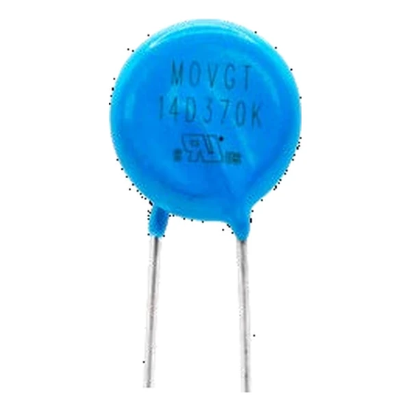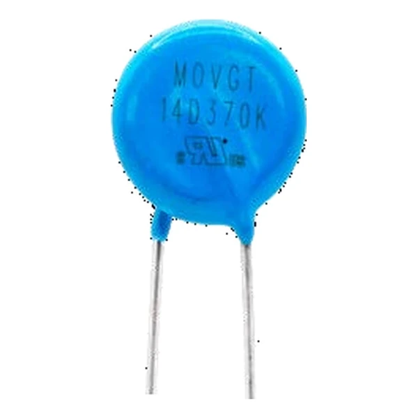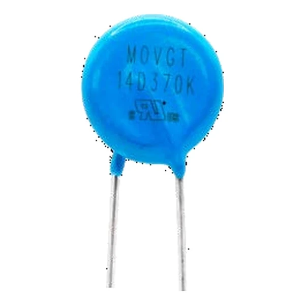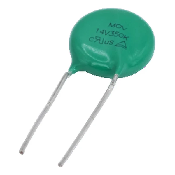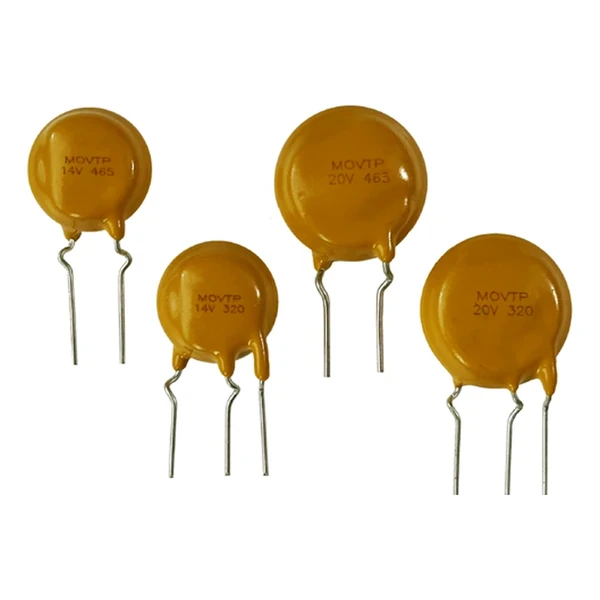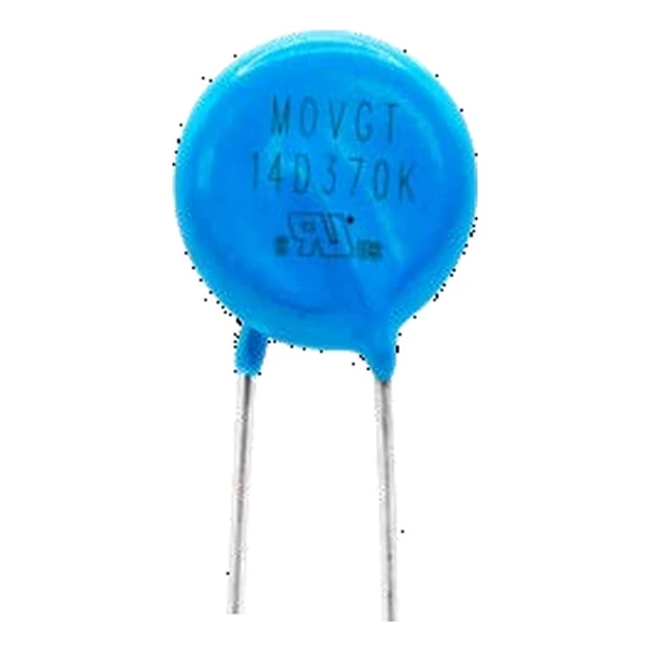
Eaton MOVGT20V135K Integrated MOV GDT Protector
- Product Details
- Download
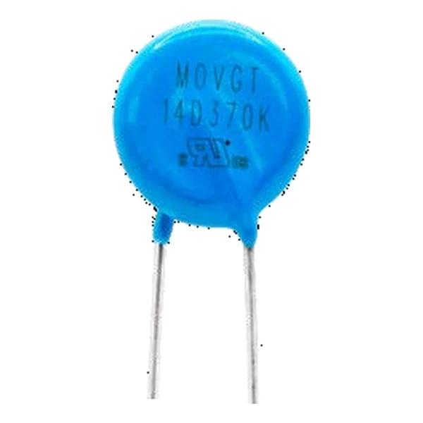
Eaton MOVGT20V135K Integrated MOV GDT Protector
Key Specifications
| Parameter | Value |
|---|---|
| Orderable part number | MOVGT20V135K |
| UL volts | 115 Vac |
| Recommended MCOV | 135 Vac |
| UL MCOV | 150 Vac |
| MOV voltage at 1 mA | 180(162~198) V |
| GDT voltage at 100 V/s | 350(280~420) V |
| Platform voltage at 1000 V/us | max. 320 V |
| Peak voltage at 1000 V/us | max. 1020 V |
| Withstand count at 2 kV / 1 kA | 40 shots |
| MOV withstand current, 8/20 us | 10000 A |
| Maximum energy, 10/1000 us | 130 J |
| Capacitance at 1 kHz | 5 pF |
| Package | 20 mm disc |
| Mounting | Radial, through-hole |
| Operating temperature | -40 °C to +105 °C |
| Qualification | Commercial grade |
| RoHS | Compliant, halogen free |
| Data sheet | Eaton Technical Data ELX1161 |
Dimensions, recommended pad or hole pattern and the derating curves are
on the data sheet pages; the package line above gives the body size as Eaton states it.
What the Numbers Mean
The two devices are stacked in one package, so the coordination is fixed by the manufacturer rather than by the board designer. That removes the usual risk of picking a GDT whose sparkover sits too close to the MOV clamp.
The MOV inside is a 180(162~198) V part and the GDT is a 350(280~420) V tube. In series the pair holds the surge at the platform voltage of 320 V, well under the peak 1020 V it would reach alone at a 1000 V/us edge.
Withstand is quoted as 40 shots at 2 kV / 1 kA. Because the GDT carries the follow current, the MOV is not eroded by the long tail of the pulse the way a stand-alone varistor is.
Within the MOVGT family this is item 130 of 160 in the Eaton catalogue.
Where This Series Fits
The part is the first thing the surge sees, so it sits between the inlet and the fuse only if the fuse is rated for the follow current; otherwise the fuse goes first and the protector after it.
- The GDT will not extinguish at DC. On a DC input the follow current keeps the tube conducting until the source is interrupted, so this part belongs on AC mains only.
- The MOV inside is a disc, so the energy rating follows the disc diameter; the GDT adds current capability, not joules.
Frequently Asked Questions
Why put a GDT in series with a MOV?
The MOV triggers fast and the GDT clamps low. In series the MOV starts the conduction and the GDT carries the current, so the residual voltage is closer to the GDT arc voltage than to the MOV clamp.
What keeps the GDT from firing on the normal line voltage?
The MOV holds off the continuous voltage, so the GDT only sees the line when the MOV is conducting. That coordination is what allows the series stack to sit across mains.
How many surges will it take?
The withstand column states the count at 2 kV / 1 kA, typically 40 shots. That is the number to design against, not the single-shot peak current of the MOV inside.
Shenzhen Gaorunxin Technology Co., Ltd
Online message
Shenzhen Gaorunxin Technology Co., Ltd