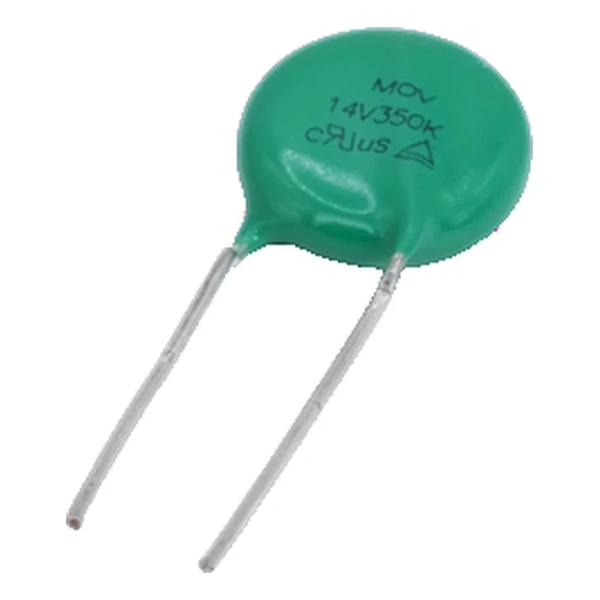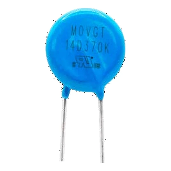
Eaton MOVGT20V370K MOV / GDT Device 370 Vac
- Product Details
- Download
Eaton MOVGT20V370K MOV / GDT Device 370 Vac
Electrical Specifications
| Parameter | Value |
|---|---|
| Orderable part number | MOVGT20V370K |
| UL volts | 350 Vac |
| Recommended MCOV | 370 Vac |
| UL MCOV | 460 Vac |
| MOV voltage at 1 mA | 560(504~616) V |
| GDT voltage at 100 V/s | 600(480~720) V |
| Platform voltage at 1000 V/us | max. 986 V |
| Peak voltage at 1000 V/us | max. 1320 V |
| Withstand count at 2 kV / 1 kA | 40 shots |
| MOV withstand current, 8/20 us | 10000 A |
| Maximum energy, 10/1000 us | 380 J |
| Capacitance at 1 kHz | 5 pF |
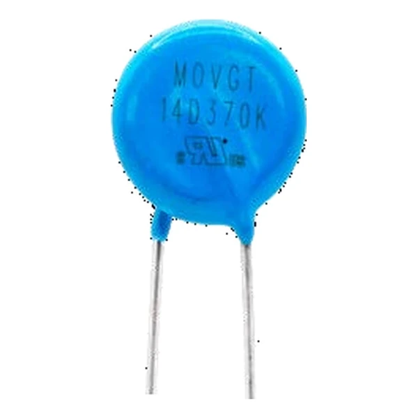
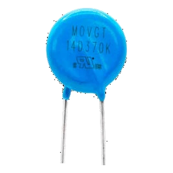
| Package | 20 mm disc |
| Mounting | Radial, through-hole |
| Operating temperature | -40 °C to +105 °C |
| Qualification | Commercial grade |
| RoHS | Compliant, halogen free |
| Data sheet | Eaton Technical Data ELX1161 |
Dimensions, recommended pad or hole pattern and the derating curves are
on the data sheet pages; the package line above gives the body size as Eaton states it.
The Figures Explained
This is a mains-input protector, not a board-level one. It is chosen for the first stage ahead of a differential filter, and its platform voltage is what the downstream 1 kV-rated parts have to survive.
The MOV inside is a 560(504~616) V part and the GDT is a 600(480~720) V tube. In series the pair holds the surge at the platform voltage of 986 V, well under the peak 1320 V it would reach alone at a 1000 V/us edge.
Withstand is quoted as 40 shots at 2 kV / 1 kA. Because the GDT carries the follow current, the MOV is not eroded by the long tail of the pulse the way a stand-alone varistor is.
Within the MOVGT family this is item 152 of 160 in the Eaton catalogue.
Where This Series Fits
The series combination goes across the input at the first stage, ahead of the filter, with the GDT on the line side. Both devices carry the surge current, so the trace between them has to be as short and as wide as the incoming conductor.
- A GDT has a statistical sparkover. The tolerance in the table is the spread over many units, not the repeatability of one unit.
- The platform voltage is the level the combination holds during the surge; size the downstream insulation against it, not against the GDT DC sparkover.
Frequently Asked Questions
Does the GDT need a separate fuse?
The follow current is limited by the source impedance and the upstream fuse. Check that the fuse clears the follow current, otherwise the tube keeps conducting after the surge.
Is the capacitance low enough for a signal line?
A few picofarads, yes, but this is a mains protector. Its package and its platform voltage are chosen for an input stage, not for a data pair.
Why put a GDT in series with a MOV?
The MOV triggers fast and the GDT clamps low. In series the MOV starts the conduction and the GDT carries the current, so the residual voltage is closer to the GDT arc voltage than to the MOV clamp.
Shenzhen Gaorunxin Technology Co., Ltd
Online message
Shenzhen Gaorunxin Technology Co., Ltd