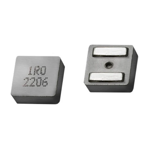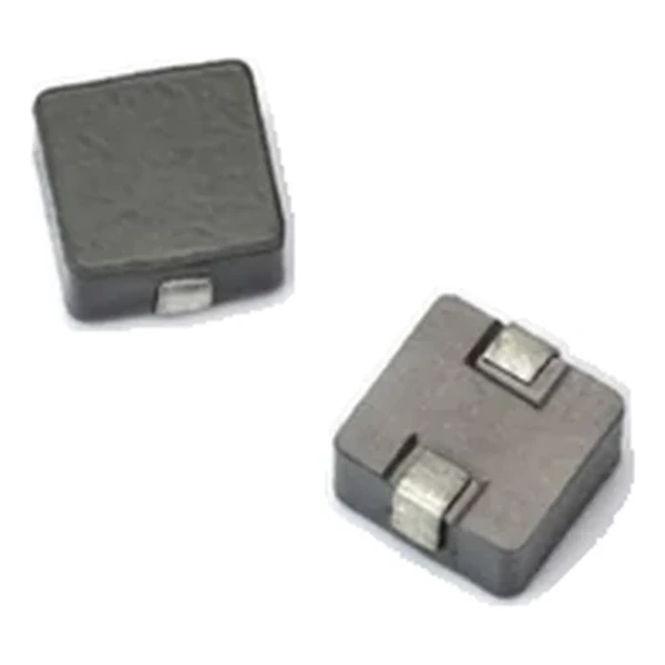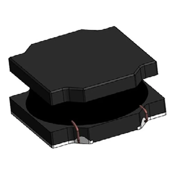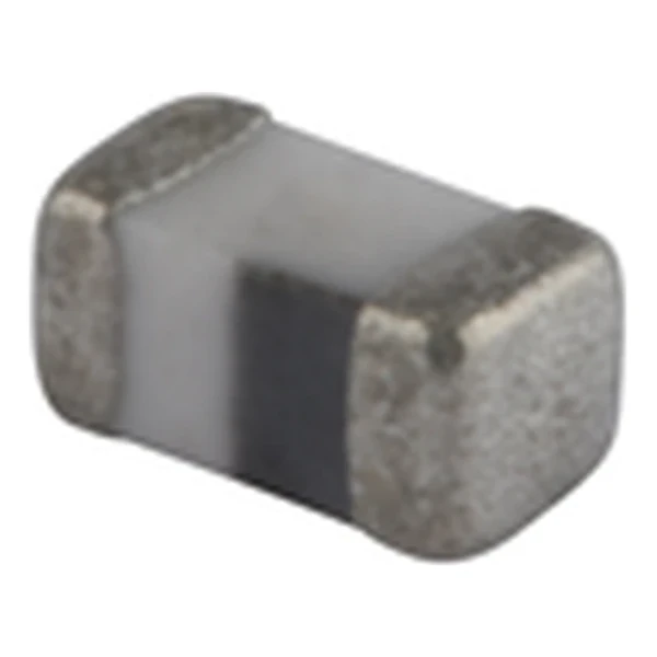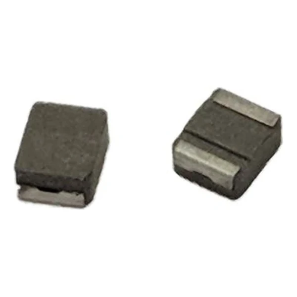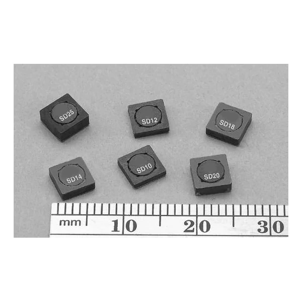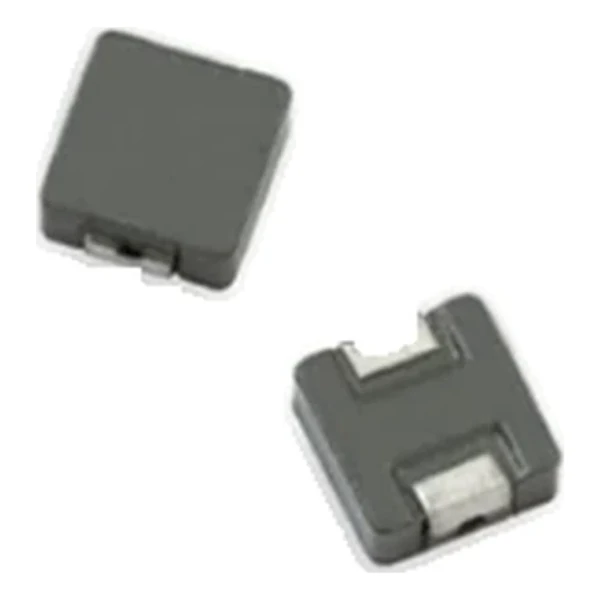
Eaton MPI5451R1-R47-R 0.47 uH AEC-Q200 Inductor 18 mOhm
- Product Details
- Download
Eaton MPI5451R1-R47-R 0.47 uH AEC-Q200 Inductor 18 mOhm
Specification Table
| Parameter | Value |
|---|---|
| Orderable part number | MPI5451R1-R47-R |
| Inductance | 0.47 uH |
| DCR typical @ +20 °C | 18 mOhm |
| Irms (DC, 40 °C rise) | 6.1 A |
| Isat | 10.9 A |
| K-factor | 995 |
| Mounting | Surface mount |
| Operating temperature | -40 °C to +125 °C |
| Qualification | Commercial grade |
| RoHS | Compliant, -R suffix |
| Data sheet | Eaton Technical Data 10247 |
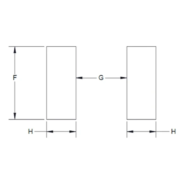
Dimensions and Pad Layout

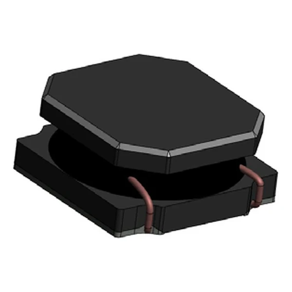
Drawing reproduced from Eaton Technical Data 10247: outline with
rated mm dimensions, pad layout and marking.
What the Numbers Mean
A molded automotive power inductor with a soft saturation curve: as current rises the inductance droops instead of collapsing, so a converter keeps control through a load step. The body is molded around the winding, which contains the field.
At 6.1 A the winding dissipates about 0.67 W in copper using the typical DCR of 18 mOhm. That is the DC floor of the loss budget – ripple and core loss come on top.
The core stores about 27.9 uJ at the saturation point, which is the energy available to bridge a load step.
The K-factor of 995 converts inductance and ripple into flux swing; read the core-loss curve at that amplitude.
Within the MPI5451R1 family this is value 2 of 11, in a range from 0.33 uH to 15 uH.
Series Positioning
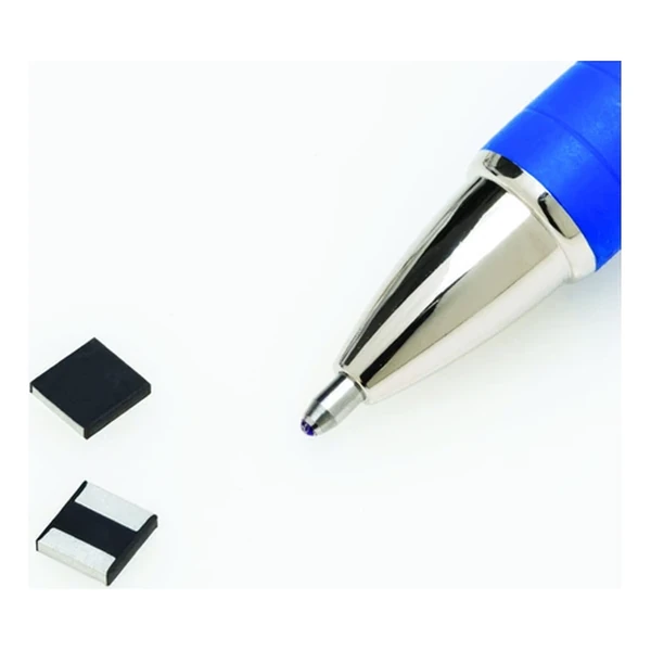
The MPIA family is the automotive miniature power range: AEC-Q200 qualified, low profile, in sizes from 2 mm to 4 mm, with both typical and maximum DCR quoted for every row.
- DCR is quoted at +20 °C; copper rises about 0.4 % per °C, so the hot loss is higher than the cold figure.
- Typical applications: handheld/mobile devices; portable media players; mp3 players; battery operated devices; notebook/netbook.
- Design note: ripple from OCL, thermal from Irms, transient from Isat. Three numbers, three checks.
Frequently Asked Questions
Why two DCR columns?
Typical and maximum. A guaranteed thermal design uses the maximum; a nominal efficiency calculation can use the typical.
Why two DCR columns?
Typical and maximum. A guaranteed thermal design uses the maximum; a nominal efficiency calculation can use the typical.
Why two DCR columns?
Typical and maximum. A guaranteed thermal design uses the maximum; a nominal efficiency calculation can use the typical.
Shenzhen Gaorunxin Technology Co., Ltd
Online message
Shenzhen Gaorunxin Technology Co., Ltd