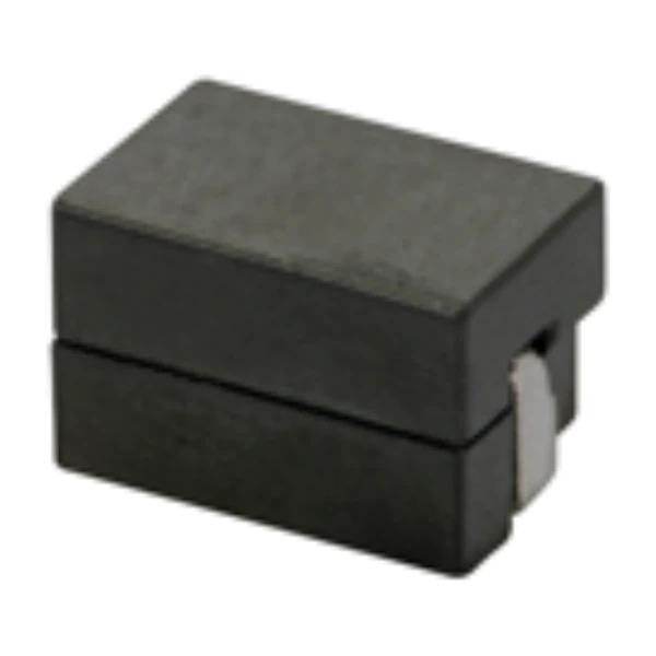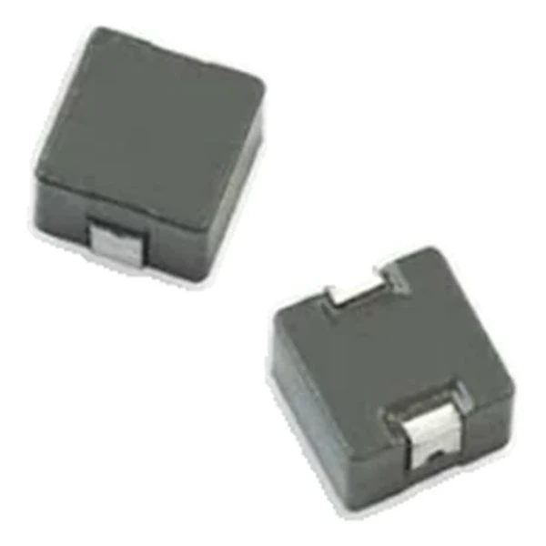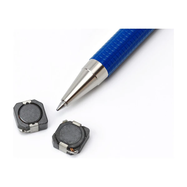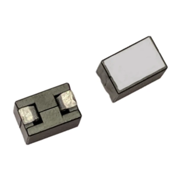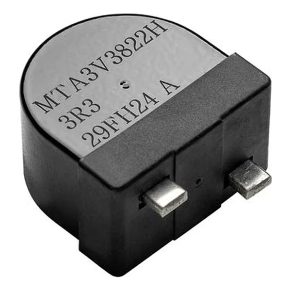
Eaton MTA3V5153H-2R2-R 2.2 uH Molded Inductor, 160 A
- Product Details
- Download
Eaton MTA3V5153H-2R2-R 2.2 uH Molded Inductor, 160 A
Specification Table
| Parameter | Value |
|---|---|
| Orderable part number | MTA3V5153H-2R2-R |
| Inductance | 2.2 uH |
| FLL minimum (at Isat) | 1.23 uH |
| DCR typical @ +20 °C | 0.21 mOhm |
| DCR maximum @ +20 °C | 0.24 mOhm |
| Irms (DC, 40 °C rise) | 160 A |
| Isat | 390 A |
| SRF typical | 16.6 MHz |
| K-factor | 7.56 |
| Mounting | Through-hole |
| Operating temperature | -55 °C to +155 °C |
| Qualification | AEC-Q200 |
| RoHS | Compliant, -R suffix |
| Data sheet | Eaton Technical Data ELX1530 |
Mechanical Drawing

Drawing reproduced from Eaton Technical Data ELX1530: outline with
rated mm dimensions, pad layout and marking.
What the Numbers Mean
Through-hole mounting here is a thermal decision as much as a mechanical one: the leads take the heat into the copper, and the body can be larger than a reflow part because there is no standoff constraint.
At 160 A the winding dissipates about 5.38 W in copper using the typical DCR of 0.21 mOhm. That is the DC floor of the loss budget – ripple and core loss come on top.
The core stores about 167310 uJ at the saturation point, which is the energy available to bridge a load step.
Self-resonance is 16.6 MHz typical. Keep the operating band, and the harmonics that carry energy, below it.
The K-factor of 7.56 converts inductance and ripple into flux swing; read the core-loss curve at that amplitude.
Within the MTA3V5153H family this is value 1 of 3, in a range from 2.2 uH to 3.3 uH.
Series Positioning
The MTA family is the molded through-hole high-current range: AEC-Q200 qualified, with two Irms and two Isat columns for thermal and transient checks.
- Through-hole joints carry the full current. Check the solder joint and barrel against the rating, not just the body.
- Typical applications: digital instrument cluster; electronic stability control system (esc); engine and powertrain systems; electric pumps, motor control and auxiliaries; powertrain control unit (pcu)/engine control unit (ecu).
- Design note: check the joint temperature in the thermal test, not the body temperature.
Frequently Asked Questions
What is the SRF column for?
It marks where the winding capacitance takes over. Keep the switching frequency and its harmonics below it.
Why through-hole for this current level?
The leads carry heat into the board copper and the body is not limited by reflow standoff, which is how the part reaches its current rating.
Is the body shielded?
The molding encloses the winding, so the external field is small.
Shenzhen Gaorunxin Technology Co., Ltd
Online message
Shenzhen Gaorunxin Technology Co., Ltd