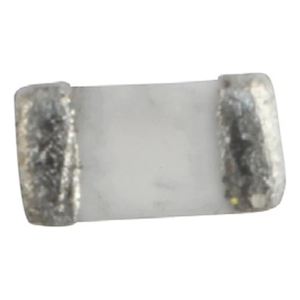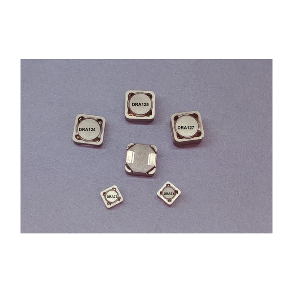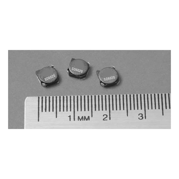
Eaton SD53-3R3-R 3.3 uH Shielded Inductor, 2.26 A
- Product Details
- Download
Eaton SD53-3R3-R 3.3 uH Shielded Inductor, 2.26 A
Ratings at a Glance
| Parameter | Value |
|---|---|
| Orderable part number | SD53-3R3-R |
| Inductance | 3.3 uH |
| DCR typical @ +20 °C | 29 mOhm |
| DCR maximum @ +20 °C | 34 mOhm |
| Irms (DC, 40 °C rise) | 2.26 A |
| Isat | 2.6 A |
| K-factor | 28 |
| Mounting | Surface mount |
| Operating temperature | -40 °C to +125 °C |
| Qualification | Commercial grade |
| RoHS | Compliant, -R suffix |
| Data sheet | Eaton Technical Data 4149 |
Dimensions and Pad Layout

Drawing reproduced from Eaton Technical Data 4149: outline with
rated mm dimensions, pad layout and marking.
How to Read These Ratings
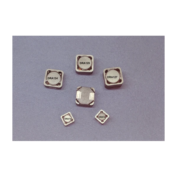
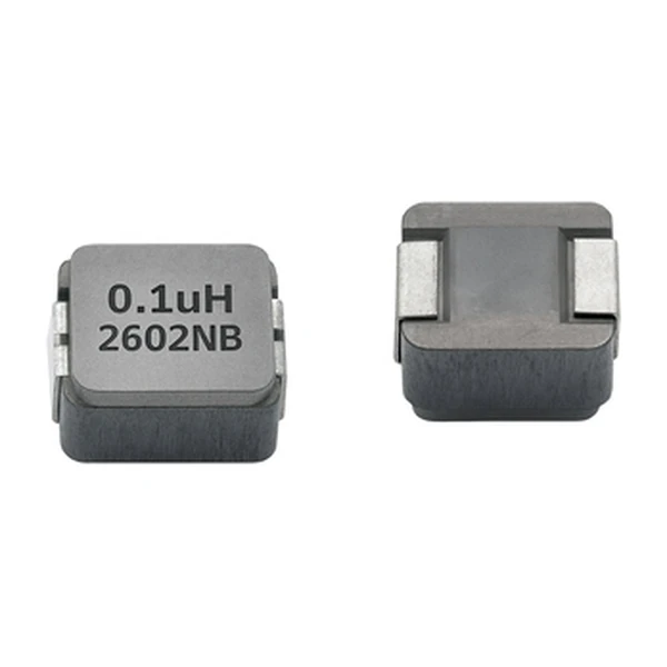
A shielded drum core inductor: the winding sits on a drum-shaped ferrite core and a shield sleeve closes the magnetic path around it. That is what keeps the radiated field low enough to place the part next to other circuitry.
At 2.26 A the winding dissipates about 0.148 W in copper using the typical DCR of 29 mOhm. That is the DC floor of the loss budget – ripple and core loss come on top.
The core stores about 11.2 uJ at the saturation point, which is the energy available to bridge a load step.
The K-factor of 28 converts inductance and ripple into flux swing; read the core-loss curve at that amplitude.
Within the SD53 family this is value 3 of 12, in a range from 1.1 uH to 100 uH.
Positioning in the Range
The SD family is the shielded drum core range: SMD parts from about 3 mm to 8 mm, covering sub-microhenry to hundreds of microhenry at currents from a few hundred milliamps to several amps.
- The shield reduces but does not eliminate the external field. Check the layout against the EMC plan before placing sensitive traces close.
- Typical applications: desktop computers; notebook and laptop regulators; led and white led drivers; digital cameras, media devices; battery power systems.
- Design note: on a shielded drum the Isat and Irms limits can differ a lot. Size against whichever is lower for the application.
Frequently Asked Questions
Why is Isat lower than Irms on some rows?
They are different limits: Irms is thermal, Isat is magnetic. On a high-inductance part the core saturates before the winding overheats.
What is the Volt-us column?
The applied volt-time product that produces a defined core loss. It is the figure to compare against the converter waveform at the switching frequency.
Why is Isat lower than Irms on some rows?
They are different limits: Irms is thermal, Isat is magnetic. On a high-inductance part the core saturates before the winding overheats.
Shenzhen Gaorunxin Technology Co., Ltd
Online message
Shenzhen Gaorunxin Technology Co., Ltd