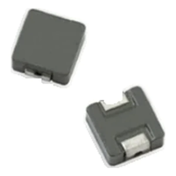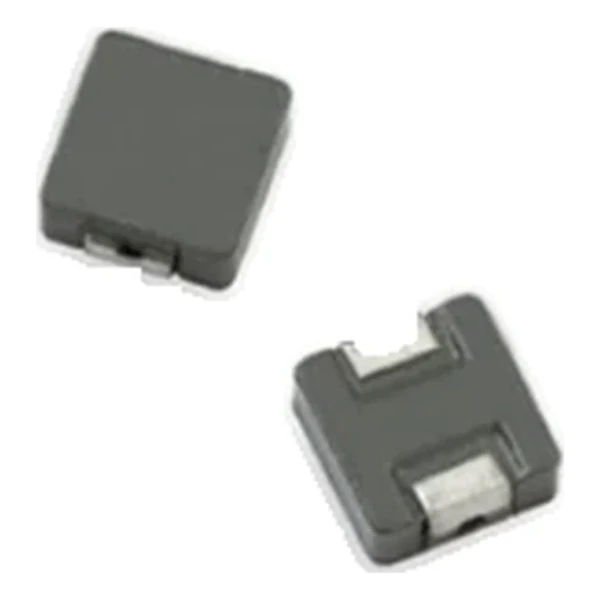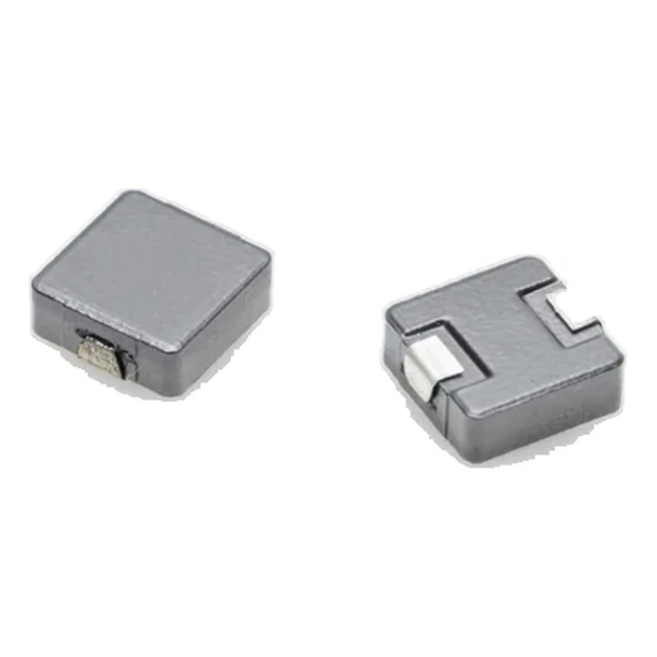
Eaton SD53-4R7-R 4.7 uH SMD Power Inductor
- Product Details
- Download
Eaton SD53-4R7-R 4.7 uH SMD Power Inductor
Electrical Specifications
| Parameter | Value |
|---|---|
| Orderable part number | SD53-4R7-R |
| Inductance | 4.7 uH |
| DCR typical @ +20 °C | 39 mOhm |
| DCR maximum @ +20 °C | 45 mOhm |
| Irms (DC, 40 °C rise) | 2.01 A |
| Isat | 2.1 A |
| K-factor | 21 |
| Mounting | Surface mount |
| Operating temperature | -40 °C to +125 °C |
| Qualification | Commercial grade |
| RoHS | Compliant, -R suffix |
| Data sheet | Eaton Technical Data 4149 |
Outline Drawing

Drawing reproduced from Eaton Technical Data 4149: outline with
rated mm dimensions, pad layout and marking.
What the Numbers Mean
The drum core concentrates the flux and the shield closes the return path, so this family behaves more like a closed-core part than an open drum while keeping the inductance-per-volume advantage of a wound component.
At 2.01 A the winding dissipates about 0.158 W in copper using the typical DCR of 39 mOhm. That is the DC floor of the loss budget – ripple and core loss come on top.
The core stores about 10.4 uJ at the saturation point, which is the energy available to bridge a load step.
The K-factor of 21 converts inductance and ripple into flux swing; read the core-loss curve at that amplitude.
Within the SD53 family this is value 4 of 12, in a range from 1.1 uH to 100 uH.
What This Family Is For
The SD family is the shielded drum core range: SMD parts from about 3 mm to 8 mm, covering sub-microhenry to hundreds of microhenry at currents from a few hundred milliamps to several amps.
- The shield reduces but does not eliminate the external field. Check the layout against the EMC plan before placing sensitive traces close.
- Typical applications: desktop computers; notebook and laptop regulators; led and white led drivers; digital cameras, media devices; battery power systems.
- Design note: on a shielded drum the Isat and Irms limits can differ a lot. Size against whichever is lower for the application.
Frequently Asked Questions
Is the part suitable for a switching converter?
Yes within its current and frequency range. Check the core loss at the switching frequency before assuming the DC rating is the limit.
Is the part suitable for a switching converter?
Yes within its current and frequency range. Check the core loss at the switching frequency before assuming the DC rating is the limit.
What is the Volt-us column?
The applied volt-time product that produces a defined core loss. It is the figure to compare against the converter waveform at the switching frequency.
Shenzhen Gaorunxin Technology Co., Ltd
Online message
Shenzhen Gaorunxin Technology Co., Ltd