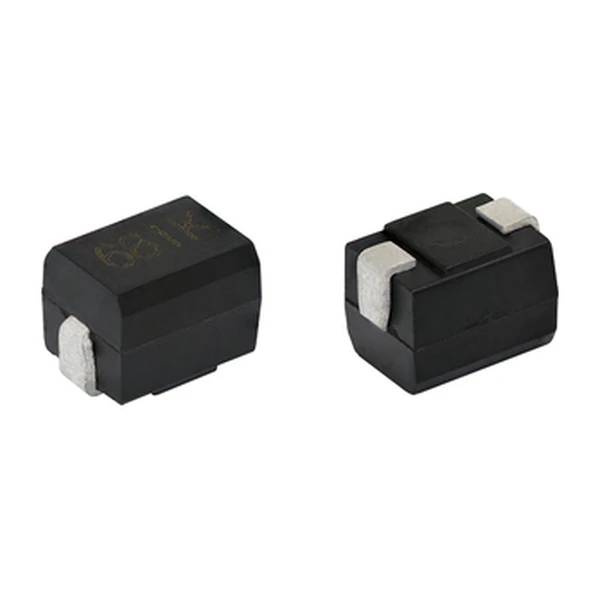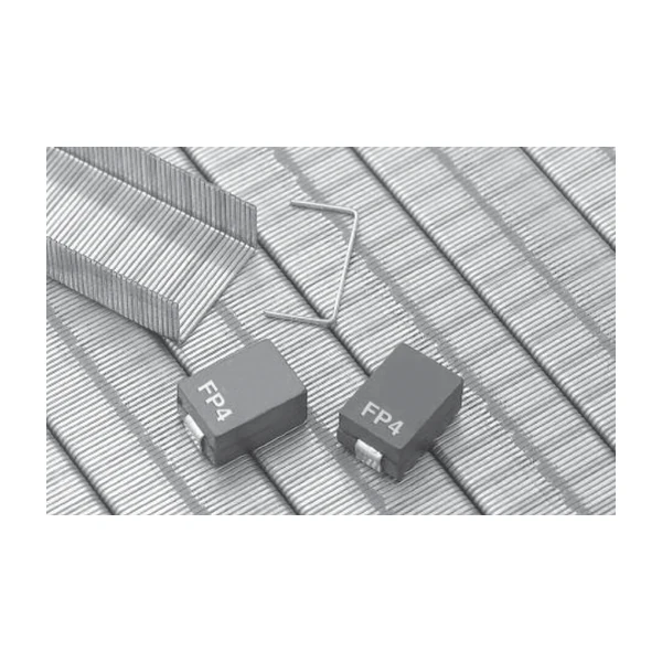
Eaton SDCH1V8040-6R8M-R 6.8 uH SMD Inductor, Isat 5.1 A
- Product Details
- Download
Eaton SDCH1V8040-6R8M-R 6.8 uH SMD Inductor, Isat 5.1 A
Specification Table
| Parameter | Value |
|---|---|
| Orderable part number | SDCH1V8040-6R8M-R |
| Inductance | 6.8 uH ±20% |
| FLL minimum (at Isat) | 3.54 uH |
| DCR typical @ +20 °C | 26 mOhm |
| DCR maximum @ +20 °C | 30 mOhm |
| Irms (DC, 40 °C rise) | 3.8 A |
| Isat | 5.1 A |
| Mounting | Surface mount |
| Operating temperature | -40 °C to +125 °C |
| Qualification | Commercial grade |
| RoHS | Compliant, -R suffix |
| Data sheet | Eaton Technical Data ELX1035 |
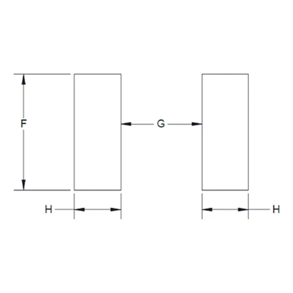
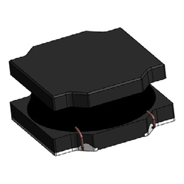
Mechanical Drawing

Drawing reproduced from Eaton Technical Data ELX1035: outline with
rated mm dimensions, pad layout and marking.
How to Read These Ratings
A semi-shielded power inductor: the winding is covered by a magnetic resin rather than a full metal shield. That damps the fringing field substantially without the cost and mass of a closed shield, and it lets the part be built in a low profile.
At 3.8 A the winding dissipates about 0.375 W in copper using the typical DCR of 26 mOhm. That is the DC floor of the loss budget – ripple and core loss come on top.
The core stores about 88.4 uJ at the saturation point, which is the energy available to bridge a load step.
Within the SDCH1V8040 family this is value 6 of 19, in a range from 1 uH to 1000 uH.
Where This Series Fits
The SDC family is the semi-shielded range: low-profile SMD inductors from about 2 mm to 6 mm, aimed at compact DC-DC converters where a full shield is not needed.
- Semi-shielded parts radiate more than closed-shield parts. If the board fails EMC, this is one of the first components to check.
- Typical applications: dc-dc converters; switching controllers; industrial iot equipment; game consoles; portable electronics.
- Design note: semi-shielded parts are the compromise between radiated field and cost. Verify the EMC margin early.
Frequently Asked Questions
Why quote both Irms and Isat?
Because they describe different failure modes: overheating and saturation. A design has to satisfy both.
How much shielding does semi-shielded give?
Enough to damp the fringing field substantially, but less than a closed metal shield. For EMC-critical layouts check the radiated field against the test plan.
Is the inductance stable with temperature?
The tolerance is quoted over the operating range; the drift inside that band is small for a wound ferrite part.
Shenzhen Gaorunxin Technology Co., Ltd
Online message
Shenzhen Gaorunxin Technology Co., Ltd