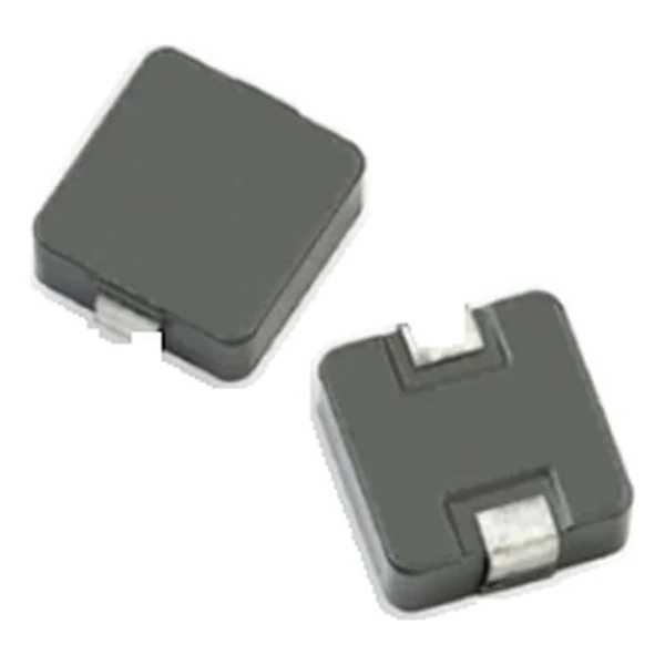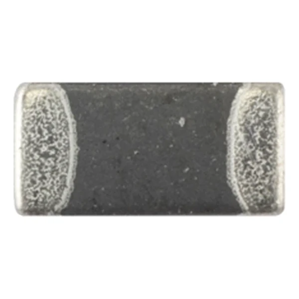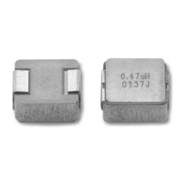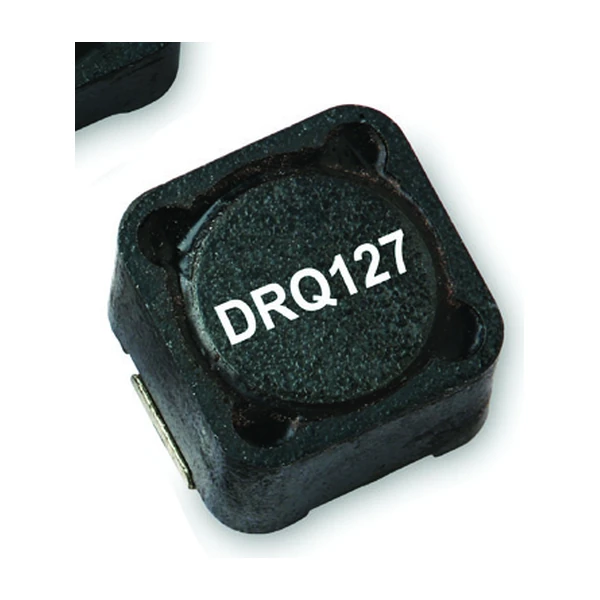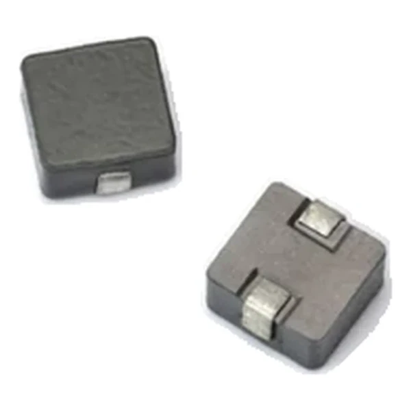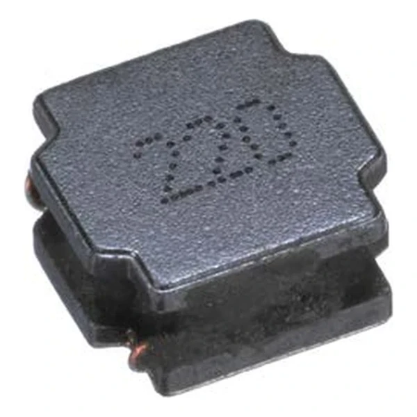
Eaton SDCHA1V8040-2R2-R 2.2 uH Semi-Shielded Automotive Inductor
- Product Details
- Download
Eaton SDCHA1V8040-2R2-R 2.2 uH Semi-Shielded Automotive Inductor
Ratings at a Glance
| Parameter | Value |
|---|---|
| Orderable part number | SDCHA1V8040-2R2-R |
| Inductance | 2.2 uH ±20% |
| FLL minimum (at Isat) | 1.23 uH |
| DCR typical @ +20 °C | 11.5 mOhm |
| Irms (DC, 40 °C rise) | 7.4 A |
| Isat | 9.8 A |
| SRF typical | 57 MHz |
| Mounting | Surface mount |
| Operating temperature | -55 °C to +125 °C |
| Qualification | AEC-Q200 |
| RoHS | Compliant, -R suffix |
| Data sheet | Eaton Technical Data ELX1097 |
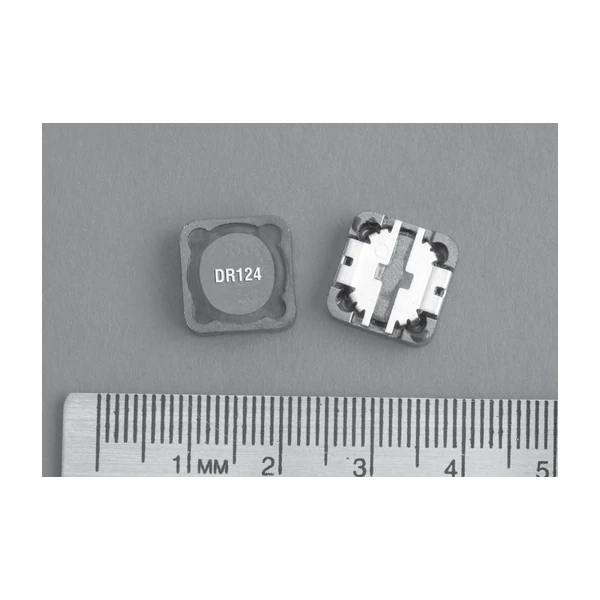
Outline Drawing

Drawing reproduced from Eaton Technical Data ELX1097: outline with
rated mm dimensions, pad layout and marking.
What the Numbers Mean
The automotive version of the semi-shielded power inductor: AEC-Q200 qualified, characterised over the full temperature range, and built with a magnetic resin shield that keeps radiated emissions low in a dense module.
At 7.4 A the winding dissipates about 0.63 W in copper using the typical DCR of 11.5 mOhm. That is the DC floor of the loss budget – ripple and core loss come on top.
The core stores about 106 uJ at the saturation point, which is the energy available to bridge a load step.
Self-resonance is 57 MHz typical. Keep the operating band, and the harmonics that carry energy, below it.
Within the SDCHA1V8040 family this is value 3 of 16, in a range from 1 uH to 100 uH.
Series Positioning
The SDCA family is the automotive semi-shielded range: the same construction as the commercial parts, qualified to AEC-Q200 and characterised across the temperature range.
- Qualification covers the part, not the module. The thermal design of the board is still the engineer’s job.
- Typical applications: led lighting; advanced driver assistance systems (adas); adaptive cruise control (acc); collision avoidance; infotainment and cluster electronics.
- Design note: use the maximum DCR at the hot corner for the loss budget, and Isat at the same temperature for the transient.
Frequently Asked Questions
How do I check the hot corner?
Use Isat at the highest operating temperature and the maximum DCR at that temperature. The room-temperature row is the optimistic one.
How do I check the hot corner?
Use Isat at the highest operating temperature and the maximum DCR at that temperature. The room-temperature row is the optimistic one.
What is the FLL column for?
Full-load inductance at saturation current. Use it for the ripple calculation at maximum load rather than the zero-bias value.
Shenzhen Gaorunxin Technology Co., Ltd
Online message
Shenzhen Gaorunxin Technology Co., Ltd