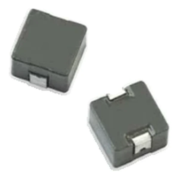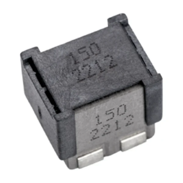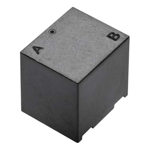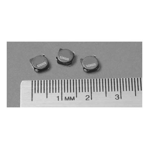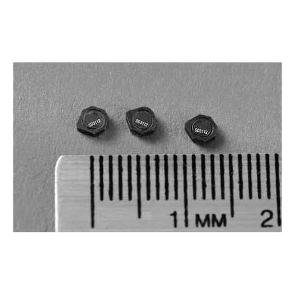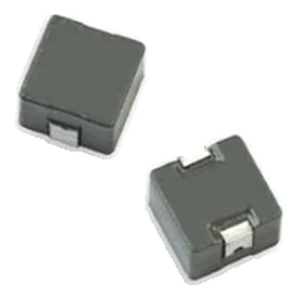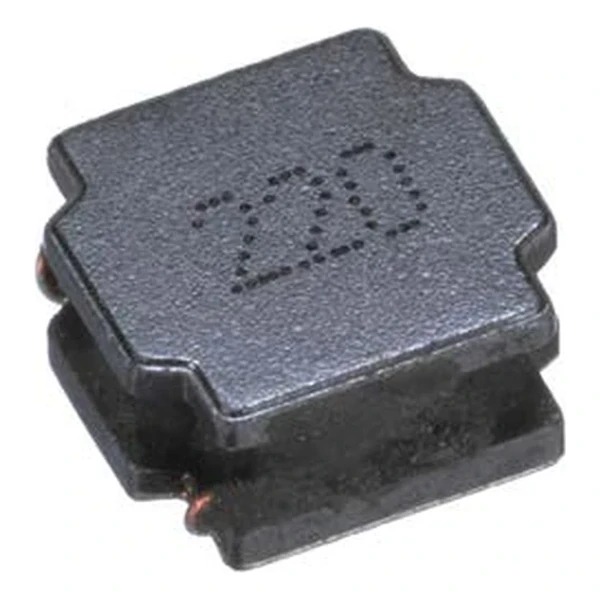
Eaton SDCHA1V8040-560-R 56 uH Automotive Inductor 160 mOhm
- Product Details
- Download
Eaton SDCHA1V8040-560-R 56 uH Automotive Inductor 160 mOhm
Specification Table
| Parameter | Value |
|---|---|
| Orderable part number | SDCHA1V8040-560-R |
| Inductance | 56 uH ±20% |
| FLL minimum (at Isat) | 31.4 uH |
| DCR typical @ +20 °C | 160 mOhm |
| Irms (DC, 40 °C rise) | 1.75 A |
| Isat | 1.9 A |
| SRF typical | 10.5 MHz |
| Mounting | Surface mount |
| Operating temperature | -55 °C to +125 °C |
| Qualification | AEC-Q200 |
| RoHS | Compliant, -R suffix |
| Data sheet | Eaton Technical Data ELX1097 |
Dimensions and Pad Layout

Drawing reproduced from Eaton Technical Data ELX1097: outline with
rated mm dimensions, pad layout and marking.
How to Read These Ratings
Automotive DC-DC stages ask for qualified construction and predictable saturation at the hot corner. This family provides both, with a semi-shielded body that keeps the profile low and the DCR moderate.
At 1.75 A the winding dissipates about 0.49 W in copper using the typical DCR of 160 mOhm. That is the DC floor of the loss budget – ripple and core loss come on top.
The core stores about 101 uJ at the saturation point, which is the energy available to bridge a load step.
Self-resonance is 10.5 MHz typical. Keep the operating band, and the harmonics that carry energy, below it.
Within the SDCHA1V8040 family this is value 13 of 16, in a range from 1 uH to 100 uH.
Positioning in the Range
The SDCA family is the automotive semi-shielded range: the same construction as the commercial parts, qualified to AEC-Q200 and characterised across the temperature range.
- Qualification covers the part, not the module. The thermal design of the board is still the engineer’s job.
- Typical applications: led lighting; advanced driver assistance systems (adas); adaptive cruise control (acc); collision avoidance; infotainment and cluster electronics.
- Design note: use the maximum DCR at the hot corner for the loss budget, and Isat at the same temperature for the transient.
Frequently Asked Questions
What is the FLL column for?
Full-load inductance at saturation current. Use it for the ripple calculation at maximum load rather than the zero-bias value.
What is the FLL column for?
Full-load inductance at saturation current. Use it for the ripple calculation at maximum load rather than the zero-bias value.
How do I check the hot corner?
Use Isat at the highest operating temperature and the maximum DCR at that temperature. The room-temperature row is the optimistic one.
Shenzhen Gaorunxin Technology Co., Ltd
Online message
Shenzhen Gaorunxin Technology Co., Ltd