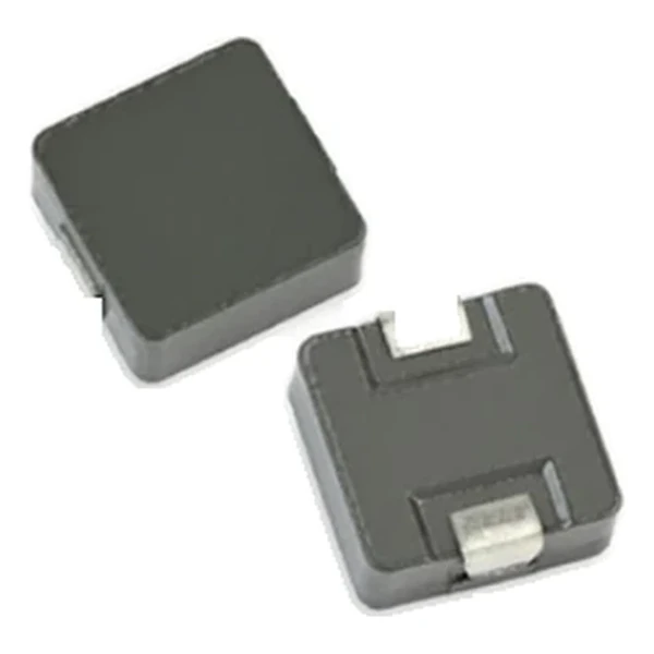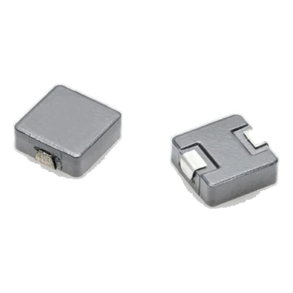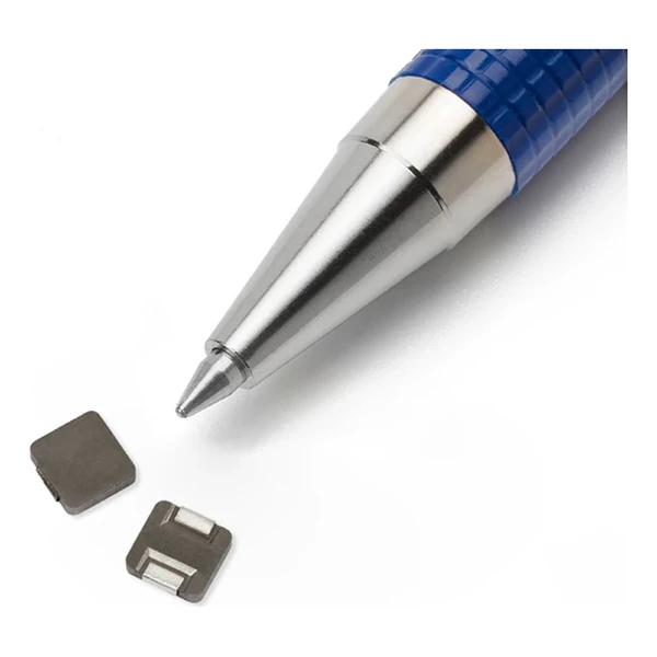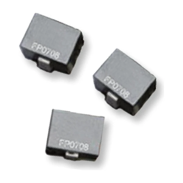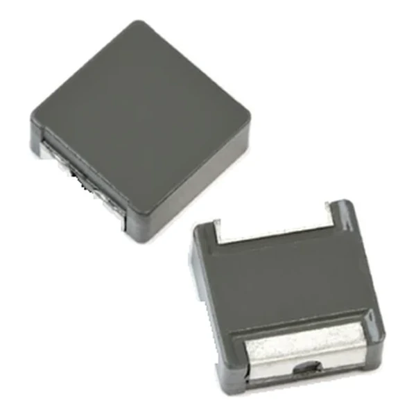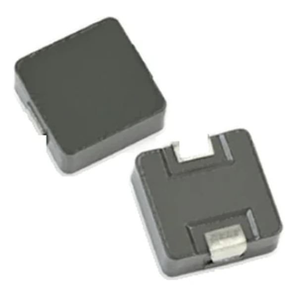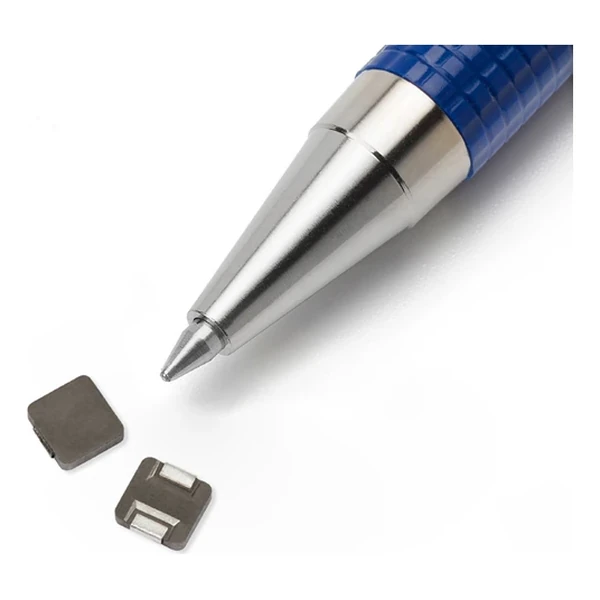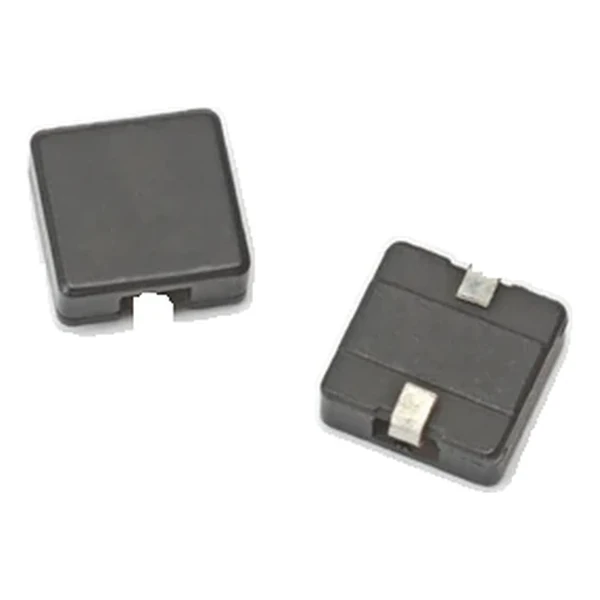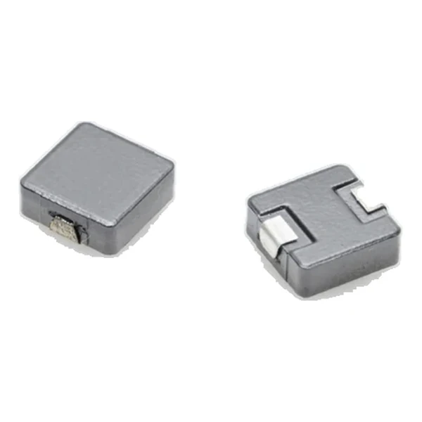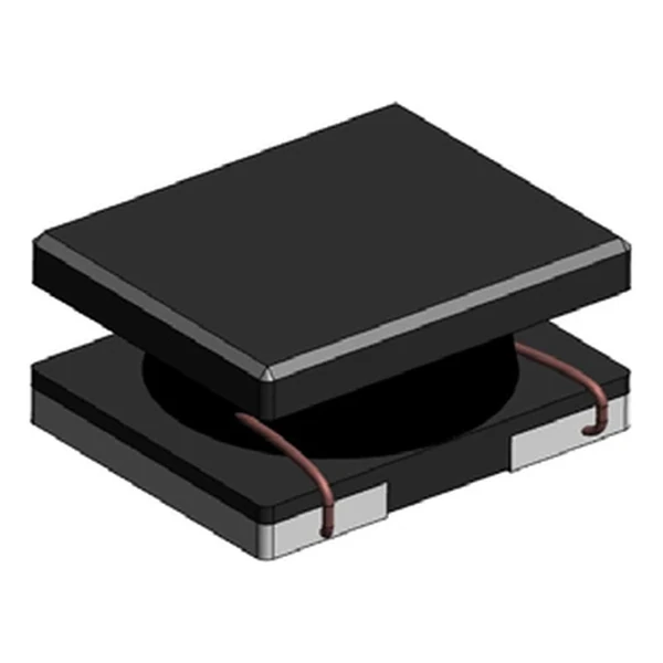
Eaton SDCL1V2010-4R7M-R 4.7 uH Semi-Shielded Inductor, 0.8 A
- Product Details
- Download
Eaton SDCL1V2010-4R7M-R 4.7 uH Semi-Shielded Inductor, 0.8 A
Electrical Specifications
| Parameter | Value |
|---|---|
| Orderable part number | SDCL1V2010-4R7M-R |
| Inductance | 4.7 uH ±20% |
| FLL minimum (at Isat) | 2.44 uH |
| DCR typical @ +20 °C | 350 mOhm |
| DCR maximum @ +20 °C | 405 mOhm |
| Irms (DC, 40 °C rise) | 0.8 A |
| Isat | 0.9 A |
| Mounting | Surface mount |
| Operating temperature | -40 °C to +125 °C |
| Qualification | Commercial grade |
| RoHS | Compliant, -R suffix |
| Data sheet | Eaton Technical Data ELX1029 |
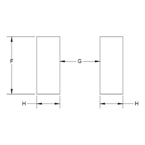
Mechanical Drawing

Drawing reproduced from Eaton Technical Data ELX1029: outline with
rated mm dimensions, pad layout and marking.
Reading the Data Sheet
This is a semi-shielded SMD power inductor, characterised with both typical and maximum DCR and with separate Irms and Isat columns. The construction is aimed at converters where the board is compact but not densely packed with magnetics.
At 0.8 A the winding dissipates about 0.224 W in copper using the typical DCR of 350 mOhm. That is the DC floor of the loss budget – ripple and core loss come on top.
The core stores about 1.9 uJ at the saturation point, which is the energy available to bridge a load step.
Within the SDCL1V2010 family this is value 7 of 10, in a range from 0.47 uH to 15 uH.
Series Positioning
The SDC family is the semi-shielded range: low-profile SMD inductors from about 2 mm to 6 mm, aimed at compact DC-DC converters where a full shield is not needed.
- Semi-shielded parts radiate more than closed-shield parts. If the board fails EMC, this is one of the first components to check.
- Typical applications: dc-dc converters; switching controllers; industrial iot equipment; game consoles; portable electronics.
- Design note: semi-shielded parts are the compromise between radiated field and cost. Verify the EMC margin early.
Frequently Asked Questions
How much shielding does semi-shielded give?
Enough to damp the fringing field substantially, but less than a closed metal shield. For EMC-critical layouts check the radiated field against the test plan.
Why quote both Irms and Isat?
Because they describe different failure modes: overheating and saturation. A design has to satisfy both.
Is the inductance stable with temperature?
The tolerance is quoted over the operating range; the drift inside that band is small for a wound ferrite part.
Shenzhen Gaorunxin Technology Co., Ltd
Online message
Shenzhen Gaorunxin Technology Co., Ltd