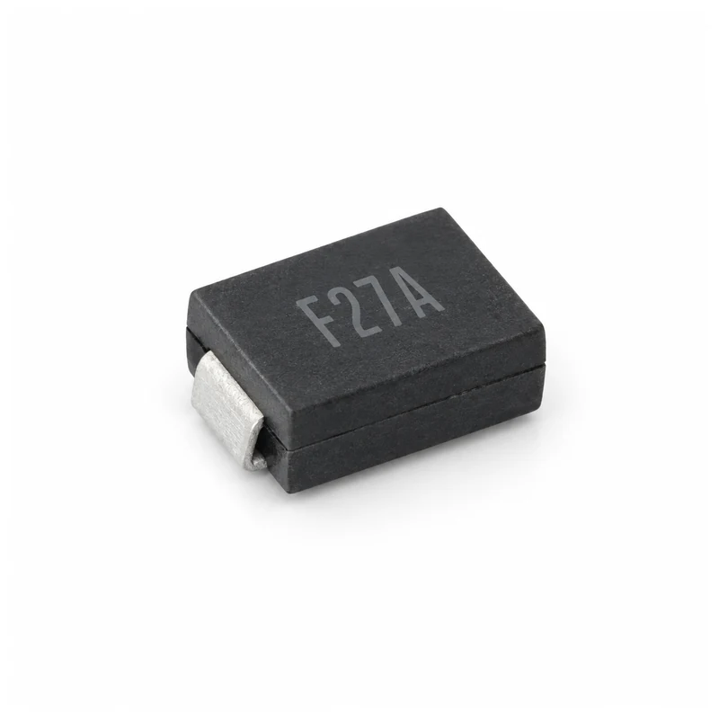
Eaton STS142700UL55 TVS Diode 70 V 150 W
- Product Details
- Download
Eaton STS142700UL55 TVS Diode 70 V 150 W
Electrical Specifications
| Parameter | Value |
|---|---|
| Orderable part number | STS142700UL55 |
| Standoff voltage (VRWM) | 70 V |
| Breakdown voltage (min / typ / max) | 85 V |
| Leakage current at VRWM | 1 uA max |
| Peak pulse power, 8/20 us, per line | 150 W |
| Forward clamping voltage at 1 A | 1.5 V |
| Forward clamping voltage at 10 A | 4 V |
| Forward clamping voltage at 24 A | 9 V |
| Junction capacitance at 1 MHz, per line | 0.55 pF typ / 1.5 pF max |
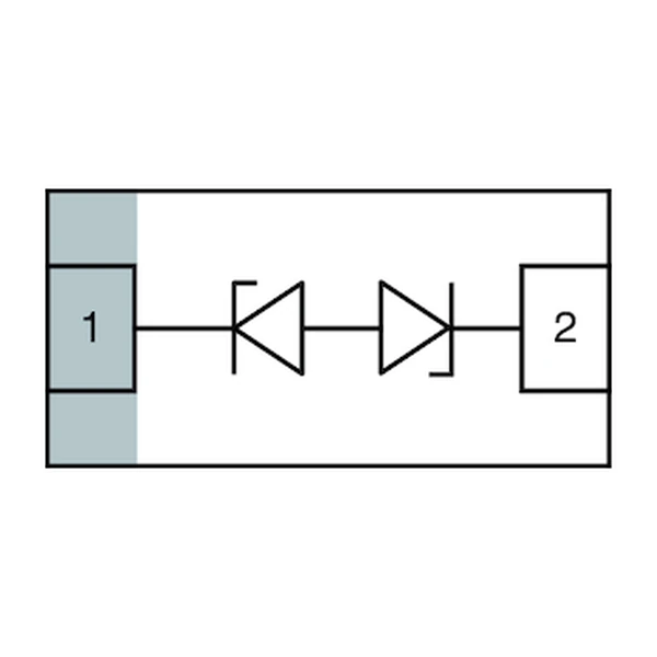
| Channels | 2 |
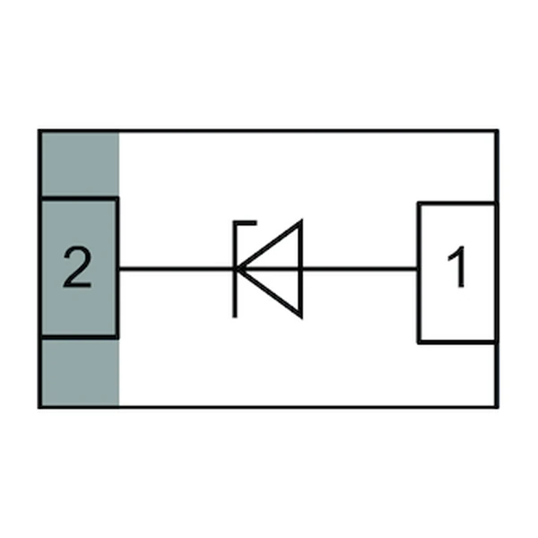
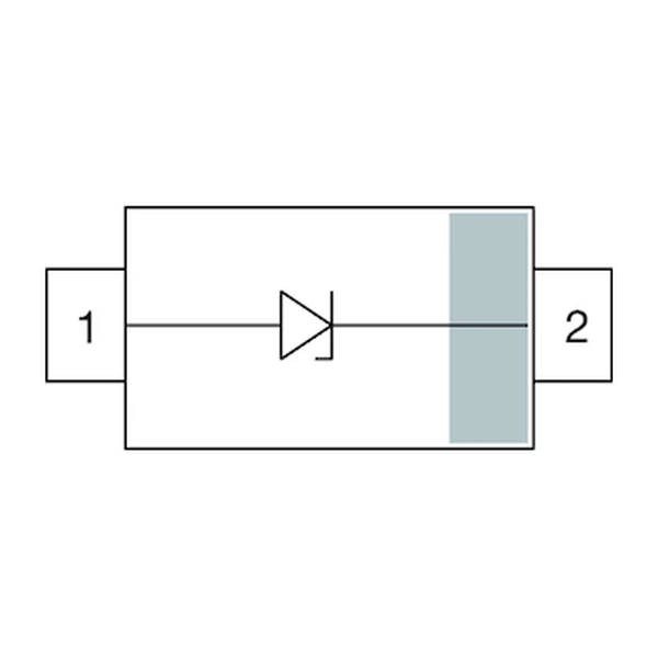
| Polarity | Unidirectional |
| ESD capability, IEC 61000-4-2 | +/-20 kV contact / +/-30 kV air |
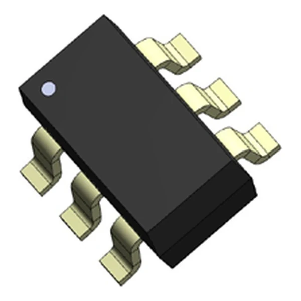
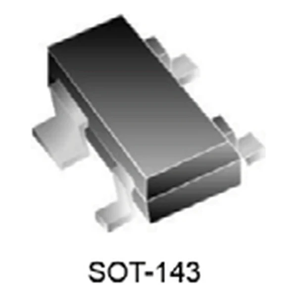
| Package | SOT-143 (S14) |
| Mounting | Surface mount |
| Moisture sensitivity level | MSL 3 |
| Operating junction temperature | -55 °C to +125 °C |
| Qualification | Commercial grade |
| RoHS | Compliant, halogen free |
| Data sheet | Eaton Technical Data 11146 |
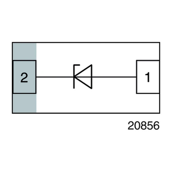
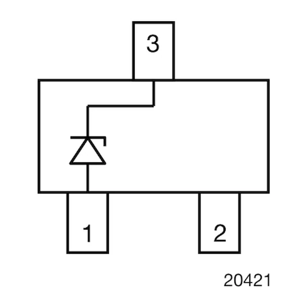
The outline drawing, pad geometry, derating curves and the pulse
waveform are on the pages of Eaton Technical Data 11146. Values above are
read directly from the electrical table for this part number, not from the family
summary.
Reading the Data Sheet
A diode array is not a fuse and not a filter. It conducts for the duration of the transient, folds the pulse down to its clamping voltage, and returns to a leakage current measured in microamps. The energy it absorbs is the pulse current times the clamp, for as long as the pulse lasts.
At 24 A the clamp sits at 9 V, or 0.13 times the 70 V standoff. The protected pin sees that figure for the duration of the pulse, so it is the one to compare with the absolute maximum in the transceiver data sheet. The 8/20 microsecond peak pulse power rating for this part is 150 W per line; the derating curve in the data sheet shortens the allowable current as the pulse gets longer.
0.55 pF per line is 289 ohms of reactance at 1 GHz and 2,894 ohms at 100 MHz. Low enough that the loading can be ignored on a high speed pair, which is what this capacitance grade is sold for.
Standing at 70 V the part draws at most 1 uA, which is 70 uW of dissipation on the line. That is the figure that matters on a battery rail that never powers down.
All 2 lines return through the common ground pin. That is the point of the array: one connection to the connector ground instead of one per line, and clamps that stay within millivolts of each other during the event.
The STS series is a diode array in a three to eight pin package: one die per line, all of them sharing a common ground pin. The working voltage is set by the process, not by a resistor divider, so the part either sits above the bus level or it does not belong on that bus at all.
Layout and Placement
Mount the array on the connector side of any series part, with the ground pin dropped straight into the connector ground plane. The trace from the pin to the array is the only path the discharge takes before the transceiver sees it, so its inductance is part of the clamp.
- The standoff voltage is a DC figure. A bus that idles at 5 V and swings to 12 V in a fault needs a part rated above 12 V, not above 5 V, or the array conducts on every fault and fails open.
- Breakdown is specified at 1 mA. The spread between minimum and maximum is production tolerance, so the design margin is measured from the minimum, not the typical.
Frequently Asked Questions
Why does the package affect the rating?
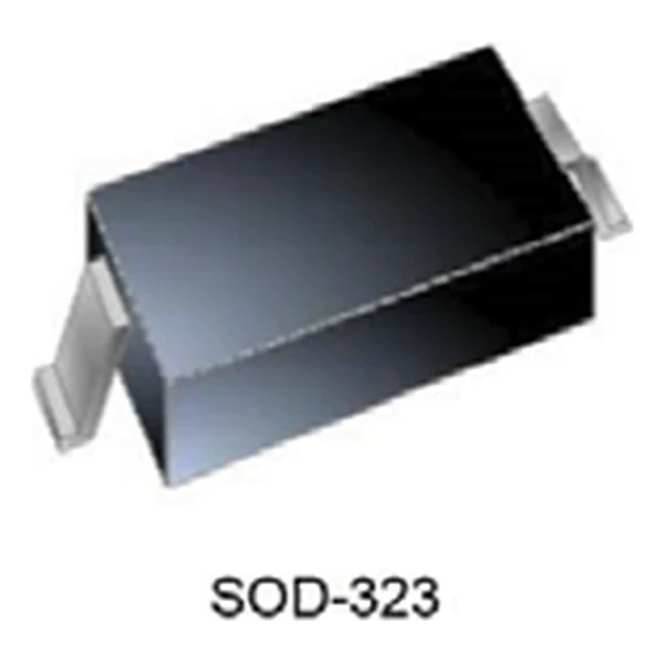
It sets the thermal mass and the lead inductance. The same die in a SOD-523 and a SOT-23 dissipates differently, so the package is part of the electrical choice rather than only a footprint decision.
Can one package protect several lines?
Yes, that is what the channel count means. The lines share a common ground pin, so the return current of all channels flows through one connection and the clamps track each other during the event.
Does the array capacitance disturb the signal?
It loads the line as a capacitor to ground. At 1 pF the reactance is about 160 ohms at 1 GHz and 1.6 kilohms at 100 MHz, which is why the low-capacitance grades are used on high speed pairs and the higher grades on slow buses.
Shenzhen Gaorunxin Technology Co., Ltd
Online message
Shenzhen Gaorunxin Technology Co., Ltd