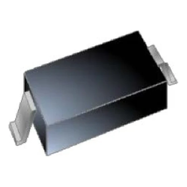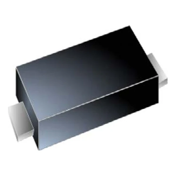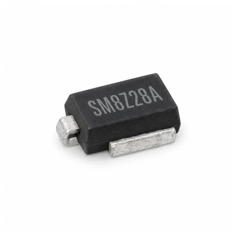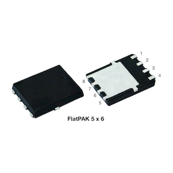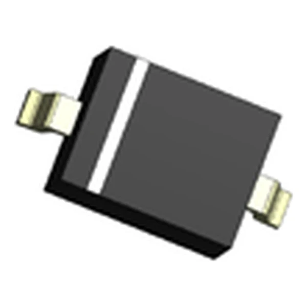
Eaton STS321070U722 TVS Diode 7 V 2000 W
- Product Details
- Download
Eaton STS321070U722 TVS Diode 7 V 2000 W
Specification Table
| Parameter | Value |
|---|---|
| Orderable part number | STS321070U722 |
| Standoff voltage (VRWM) | 7 V |
| Breakdown voltage (min / typ / max) | 7.5 V / 8 V / 9 V |
| Leakage current at VRWM | 1 uA max |
| Peak pulse power, 8/20 us, per line | 2000 W |
| Clamping voltage at 50 A | 15 V |
| Clamping voltage at 100 A | 18 V |
| Junction capacitance at 1 MHz, per line | 720 pF typ / 900 pF max |
| Channels | 1 |
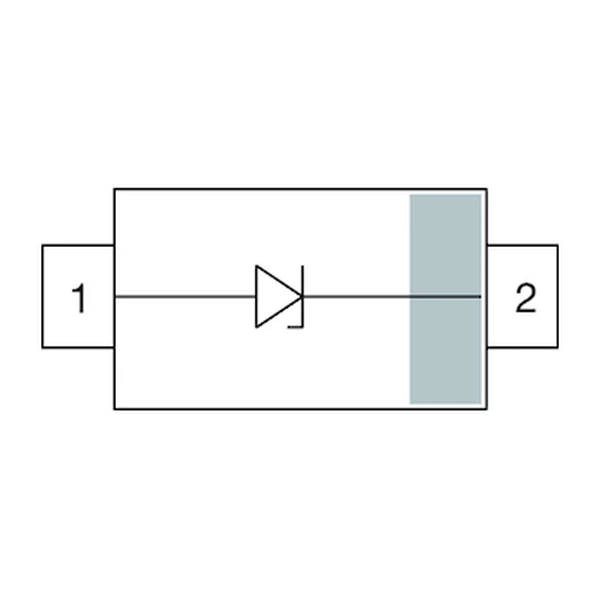
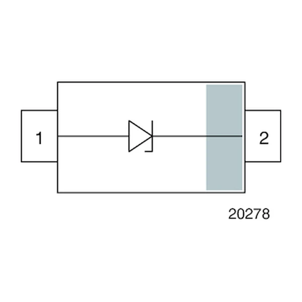
| Polarity | Unidirectional |
| ESD capability, IEC 61000-4-2 | +/-30 kV contact / +/-30 kV air |
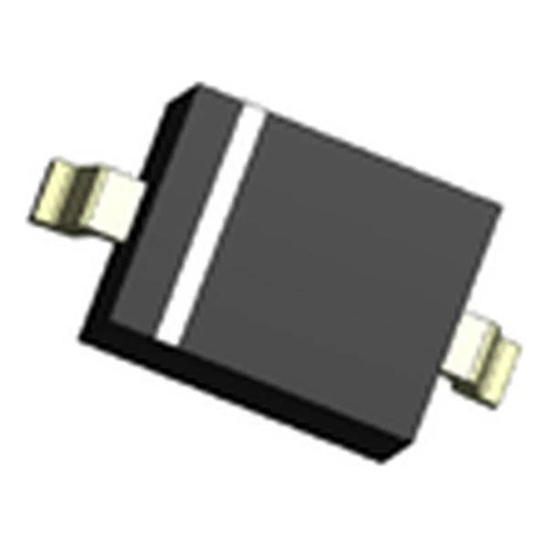
| Package | SOD-323 (S32) |
| Mounting | Surface mount |
| Moisture sensitivity level | MSL 3 |
| Operating junction temperature | -55 °C to +125 °C |
| Qualification | Commercial grade |
| RoHS | Compliant, halogen free |
| Data sheet | Eaton Technical Data 11145 |
The outline drawing, pad geometry, derating curves and the pulse
waveform are on the pages of Eaton Technical Data 11145. Values above are
read directly from the electrical table for this part number, not from the family
summary.
How to Read These Ratings
Two numbers decide whether an array fits a port. The standoff voltage has to clear the highest steady level the line can hold, and the clamping voltage at the surge current has to stay under the absolute maximum of the transceiver behind it. Everything else on the data sheet is a consequence of those two.
At 100 A the clamp sits at 18 V, or 2.57 times the 7 V standoff. The protected pin sees that figure for the duration of the pulse, so it is the one to compare with the absolute maximum in the transceiver data sheet. The 8/20 microsecond peak pulse power rating for this part is 2000 W per line; the derating curve in the data sheet shortens the allowable current as the pulse gets longer.
720 pF per line is 0.22 ohms of reactance at 1 GHz and 2.2 ohms at 100 MHz. A heavy load by design: this grade belongs on a supply rail or a low frequency line, where the capacitance is harmless and the low clamp is the point.
Standing at 7 V the part draws at most 1 uA, which is 7 uW of dissipation on the line. That is the figure that matters on a battery rail that never powers down.
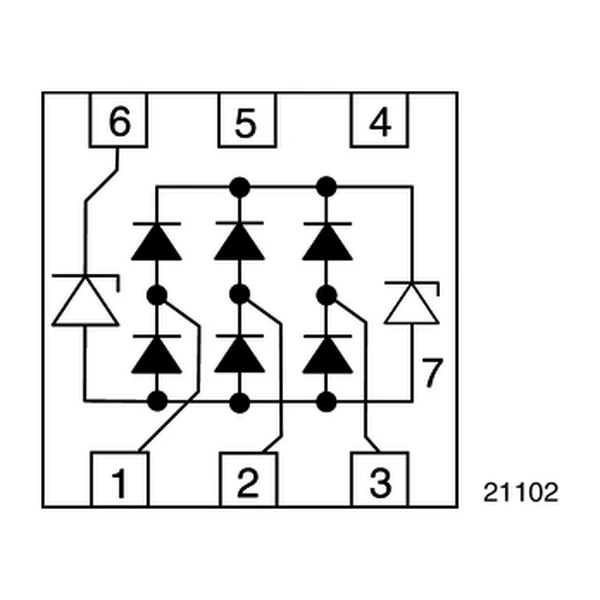
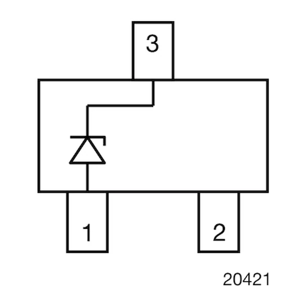
The STS series is a diode array in a three to eight pin package: one die per line, all of them sharing a common ground pin. The working voltage is set by the process, not by a resistor divider, so the part either sits above the bus level or it does not belong on that bus at all.
Board Layout
On a multi-line bus, put one array at the connector rather than one part per line spread along the board. The lines then share a single ground inductance, and the clamps stay within a few millivolts of each other during the event.
- ESD ratings are per IEC 61000-4-2 with the part as the first element the discharge meets. A connector shell or a mounting post that offers an easier path takes the strike instead, and the array never conducts.
- Peak pulse power is an 8/20 microsecond figure per line. A longer waveform allows less current and a shorter one more; the derating curve in the data sheet converts between them and is the number to use when the surge is not the standard one.
Frequently Asked Questions
How is the working voltage chosen?
Above the highest steady state voltage the line can reach, including the fault levels the standard for that interface allows. Then confirm the minimum breakdown voltage is still above that level, because production spread moves it down.
Why does the clamp voltage differ from the breakdown voltage?
Breakdown is measured at 1 mA. The clamp is measured at the pulse current, which can be tens of amps, and the difference is the dynamic resistance of the junction multiplied by that current.
Does the array capacitance disturb the signal?
It loads the line as a capacitor to ground. At 1 pF the reactance is about 160 ohms at 1 GHz and 1.6 kilohms at 100 MHz, which is why the low-capacitance grades are used on high speed pairs and the higher grades on slow buses.
Shenzhen Gaorunxin Technology Co., Ltd
Online message
Shenzhen Gaorunxin Technology Co., Ltd