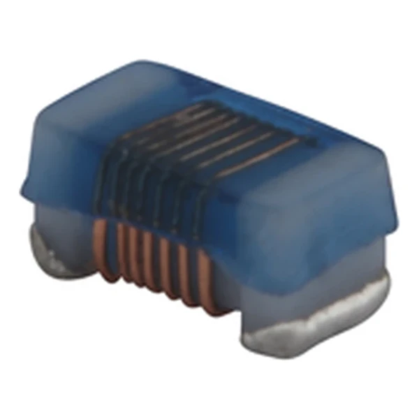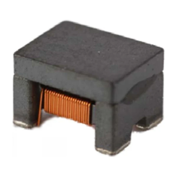
Eaton TL1211V1-R170-R 170 nH TLVR Power Inductor
- Product Details
- Download
Eaton TL1211V1-R170-R 170 nH TLVR Power Inductor
Ratings at a Glance
| Parameter | Value |
|---|---|
| Orderable part number | TL1211V1-R170-R |
| Primary inductance Lpri (terminals 3-4) | 170 nH ±10% |
| Secondary inductance Lsec (terminals 1-2) | 170 nH ±10% |
| FLL minimum at Isat1 | 122 nH |
| DCR primary @ +20 °C | 0.6 mOhm |
| DCR secondary @ +20 °C | 0.125 mOhm |
| Irms secondary (40 °C rise) | 75 A |
| Isat1 (20 % rolloff @ +25 °C) | 74 A |
| Isat2 (20 % rolloff @ +100 °C) | 64 A |
| Isat3 (20 % rolloff @ +125 °C) | 59 A |
| K-factor (Bp-p = K x L x dI x 10^-3) | 313 |
| Coupling coefficient Kps | 0.96 |
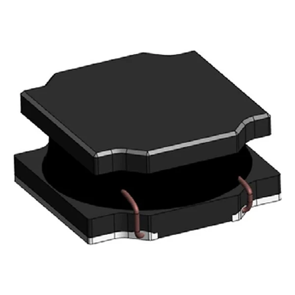
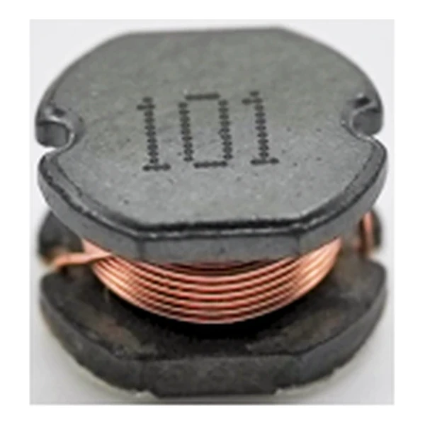
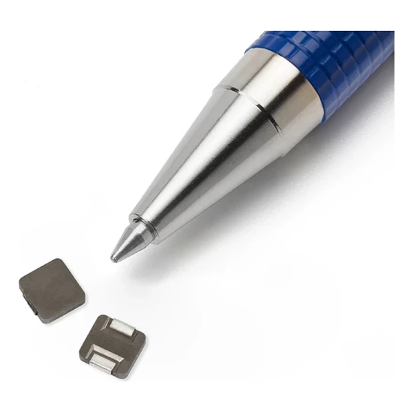
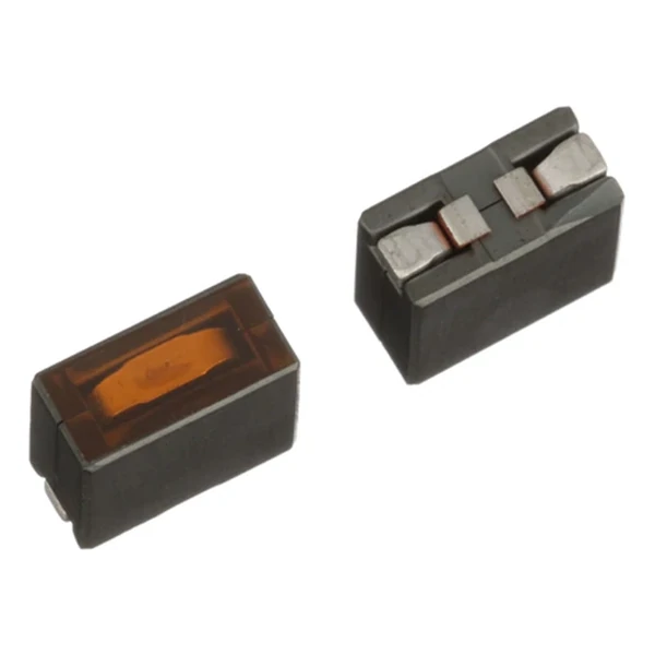
| Package | 12.0 x 6.0 mm, 11.05 mm high |
| Mounting | Surface mount |
| Operating temperature | -40 °C to +125 °C |
| Qualification | Commercial grade |
| RoHS | Compliant, -R suffix |
| Data sheet | Eaton Technical Data ELX1156 |
Dimensions and Pad Layout

Drawing reproduced from Eaton Technical Data ELX1156: outline views
with rated mm dimensions, pad layout and marking.
What the Numbers Mean
A trans-inductor regulator does not give each phase its own inductor and stop there. The secondary windings are tied into one series loop, so when a phase is driven, the loop forces every other phase to deliver current as well. The load step is shared before the controller has finished reacting.
The secondary winding drops about 9.38 mV at its 75 A rating and dissipates roughly 0.703 W there. That is the loss the loop carries on top of the phase windings.
The K-factor turns the applied ripple into a flux swing through Bp-p = K x L x delta-I, with L taken at the operating point. That amplitude, not the DC current, is what the core-loss curve is read against.
With Kps at 0.96 the two windings share the flux almost completely; the fraction that does not link is what shows up as leakage inductance in the phase.
Within the TL1211V1 family this is value 7 of 8, in a range from 70 to 200 nH.
Positioning in the Range
The TL and TLP families cover 70 nH to 200 nH of primary inductance in 9.6 x 6.4 mm, 10 x 6 mm and 12 x 6 mm bodies, with the secondary winding equal to the primary and a coupling coefficient between 0.91 and 0.95.
- The secondary loop is part of the power stage. Layout inductance in that loop shows up directly as a slower transient, so keep the return path short and symmetric between phases.
- Typical applications: multi-phase and vcore regulators; voltage regulator modules (vrms) and high power density vrms; server and desktop; central processing unit (cpu); graphics processing unit (gpu).
- Design note: ripple from FLL, transient from Kps, loss from the primary DCR at the phase current. The secondary DCR only carries the difference current.
Frequently Asked Questions
How do I estimate core loss?
Use the K-factor with the flux swing: Bp-p = K x L x delta-I x 10^-3, with L in microhenry and delta-I in amp, which gives gauss. Read the core-loss curve at that amplitude and the switching frequency.
Which inductance do I use for the ripple calculation?
FLL, the full-load inductance, because that is the value at the current the converter actually runs at. OCL is the zero-bias figure and overstates the inductance at load; using it makes the ripple look smaller than it is.
Which inductance do I use for the ripple calculation?
FLL, the full-load inductance, because that is the value at the current the converter actually runs at. OCL is the zero-bias figure and overstates the inductance at load; using it makes the ripple look smaller than it is.
Shenzhen Gaorunxin Technology Co., Ltd
Online message
Shenzhen Gaorunxin Technology Co., Ltd