Eaton WCLA1005V1-3R9-R 3.9 nH RF Chip Inductor, SRF 6000 MHz
- Product Details
- Download
Eaton WCLA1005V1-3R9-R 3.9 nH RF Chip Inductor, SRF 6000 MHz
Key Specifications
| Parameter | Value |
|---|---|
| Orderable part number | WCLA1005V1-3R9-R |
| OCL | 3.9 nH ±5% |
| Q minimum @ test frequency | 20 @ 250 MHz |
| SRF minimum | 6000 MHz |
| DCR maximum @ +25 °C | 66 mOhm |
| Rated current (20 °C rise) | 840 mA |
| OCL test frequency | 250 MHz |
| OCL test voltage | 500 mV |
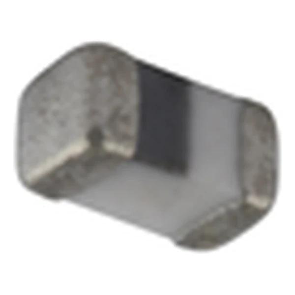
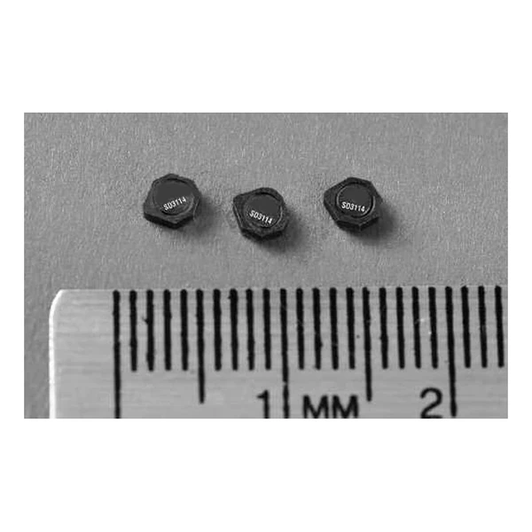
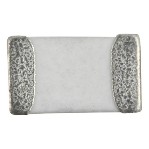
| Package | 1.19 x 0.66 mm, 0.60 mm high |
| Mounting | Surface mount |
| Operating temperature | -40 °C to +125 °C |
| Qualification | AEC-Q200 |
| RoHS | Compliant, -R suffix |
| Data sheet | Eaton Technical Data 10981 |
Mechanical Drawing

Drawing reproduced from Eaton Technical Data 10981: outline views
with rated mm dimensions, pad layout and marking.
The Figures Explained
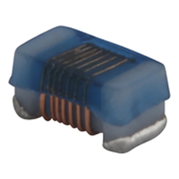
This is a wire wound chip inductor for RF and small-signal circuits: tight tolerance, defined Q, and a rated current that is set by a 20 °C self-temperature rise rather than by saturation.
At the 840 mA rating the winding drops about 55.4 mV and dissipates 46.6 mW. Both are small enough to ignore in a bias network but not in a high-Q filter.
Q of 20 at 250 MHz with self-resonance at 6000 MHz puts the useful band comfortably below the point where the winding capacitance takes over.
Within the WCLA1005V1 family this is value 13 of 52, in a range from 1 to 120 nH.
What This Family Is For
The WCL and WCLA families run from 1.0 nH in a 1.19 x 0.66 mm body to 560 uH in 3.5 x 2.9 mm, with Q quoted at a stated test frequency for every row.
- The rated current is a 20 °C rise figure, not a saturation limit. In a DC bias application check the inductance at the actual bias before sizing the filter.
- Typical applications: adas; infotainment; wireless communications; wifi, bluetooth, satellite; antenna tuning.
- Design note: read Q and SRF at the frequency the part works at, not at the test frequency printed in the table.
Frequently Asked Questions
How is Q specified?
At one test frequency, given in the table. Q falls away either side of that point, so a part quoted at 25 MHz tells you little about behaviour at 900 MHz.
How is Q specified?
At one test frequency, given in the table. Q falls away either side of that point, so a part quoted at 25 MHz tells you little about behaviour at 900 MHz.
How is Q specified?
At one test frequency, given in the table. Q falls away either side of that point, so a part quoted at 25 MHz tells you little about behaviour at 900 MHz.
Shenzhen Gaorunxin Technology Co., Ltd
Online message
Shenzhen Gaorunxin Technology Co., Ltd