Welcome to our company!



EV2696A-Q-00B 4-6V, 3A I2C Controlled Single Cell Switching Charger Evaluation Board
Share
pMPS EV2696A-Q-00B — I2C Controlled Single Cell Switching Charger, 4-6V input, 3 A output./p
- Product Details
- Download
EV2696A-Q-00B 4-6V, 3A I2C Controlled Single Cell Switching Charger Evaluation Board
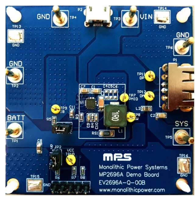
The MPS EV2696A-Q-00B is an evaluation board built around the MP2696A for bench characterisation of the device in its intended topology. It operates from a 4 V to 6 V input, is rated for 3 A and handles 1s battery stacks.
The EV2696A-Q-00B is an evaluation board for the MP2696A, a high-integrated, flexible switch- mode battery charge management and system power path management device.
Key Specifications
| Part Number | EV2696A-Q-00B |
| Board For | MP2696A |
| Board Type | Evaluation / demonstration board |
| Function | I2C Controlled Single Cell Switching Charger |
| Input Voltage | 4 V to 6 V |
| Current Rating | 3 A |
| Battery Cells | 1s |
| Interface | I²C |
| Ordering Codes | EV2696A-Q-00B |
Features
- 4.0V to 6V Operation Voltage Range
- Up to 16V Sustainable Input Voltage
- 500mA to 3.6A Programmable Charge Current
- 3.6V to 4.45V Programmable Charge Regulation Voltage
- 100mA to 3A Programmable Input Current Limit
- Minimum Input Voltage Loop for Maximum Adapter Power Tracking
- Boost-converter with Up to 3.6A Output Current
- Programmable Output Current Limit Loop
- Programmable Boost Output Voltage
- USB Output Cable Compensation
Evaluation Board
Design Notes
- The board ships in a default configuration; check the jumper and resistor options against the user guide before applying power.
- Respect the input terminal rating — most faults on evaluation boards come from an supply above the marked limit.
- Test points on the switching node and output are for a short-ground probe, not for a long oscilloscope lead.
- Where a GUI is supported, connect the dongle before power-up so the device enumerates on the I²C bus.
Common Questions
What input voltage does the EV2696A-Q-00B support?
4 V to 6 V. The rated output is 3 A.
What are the defining features of the EV2696A-Q-00B?
4.0V to 6V Operation Voltage Range Up to 16V Sustainable Input Voltage
Shenzhen Gaorunxin Technology Co., Ltd
Online message
Shenzhen Gaorunxin Technology Co., Ltd