Welcome to our company!



MP2764 4-21V Integrated Buck-Boost NVDC Charger QFN-32
Share
pMPS MP2764 — Integrated Buck-Boost NVDC Charger, 4-21V input, QFN-32./p
- Product Details
- Download
MP2764 4-21V Integrated Buck-Boost NVDC Charger QFN-32
The MPS MP2764 is a Integrated Buck-Boost NVDC Charger. It operates from a 4 V to 21 V input and switches at 1 MHz. It is supplied in a QFN-32 package.
The MP2764 is a highly integrated buck-boost charger IC with narrow-voltage DC (NVDC) power path management control and USB power delivery (PD) source mode for 2-cell to 4- cell battery pack applications.
Key Specifications
| Part Number | MP2764 |
| Function | Integrated Buck-Boost NVDC Charger |
| Input Voltage | 4 V to 21 V |
| Switching Frequency | 1 MHz |
| Interface | I²C |
| Package | QFN-32 |
| Ordering Codes | MP2764, MP2764GV-0000-Z |
Features
- All FETs Integration Buck-Boost Converter
- Seamless Mode Transition Between Buck/Boost and Buck-Boost Mode
- Configurable 500kHz to 1MHz Switching Frequency (fSW)
- Narrow-Voltage DC (NVDC) Power Path Management via External N-Channel Battery MOSFET (BATFET)
- Configurable Minimum and Maximum System Voltage Regulation
- System OVP and System Short-Circuit Protection (SCP)
- Dual-Phase Interleaving Operation for Buck Charging Mode with Current Balancing
- Ultrasonic Mode (USM) to Avoid Audible Noise
- Integrated 10-Bit Analog-to-Digital Converter (ADC) to Monitor the Voltage, Current, and Power
- Safety: o Thermal Shutdown o Battery Missing Detection o Battery Removal Detection o Battery Temperature Protection Compliant to JEITA Standard o Configurable Charge Safety Timer
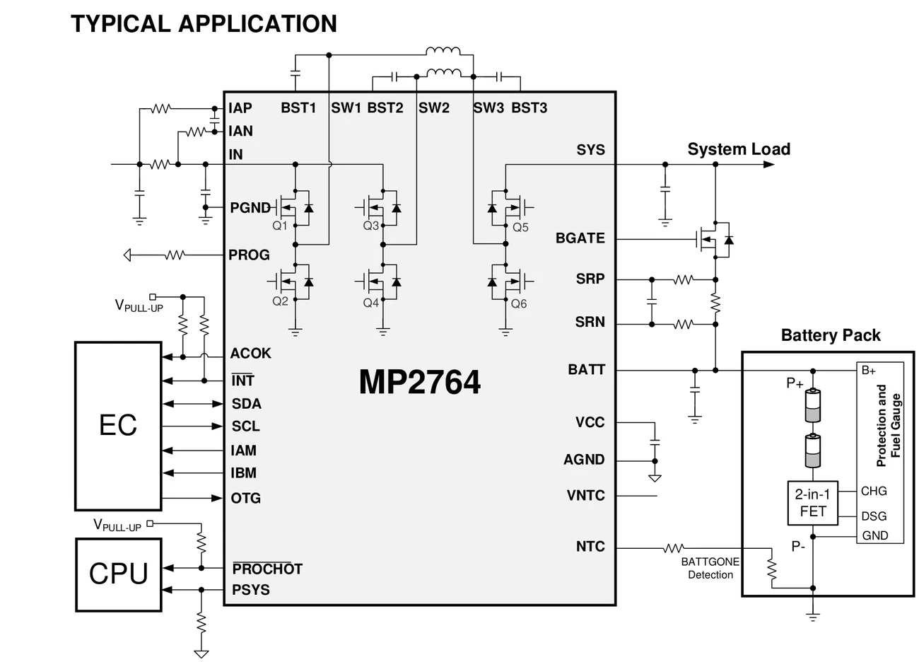
Typical Application Circuit
Applications
- Ultrabooks
Design Notes
- Charge current accuracy depends on the sense resistor tolerance, so use a 1% or better part and keep its traces Kelvin-connected.
- Wire the NTC input for JEITA profile control if the pack is charged over temperature.
- Set the input current limit to what the adapter can actually deliver; a limit above the adapter rating causes the input rail to collapse mid-charge.
- Termination current and recharge threshold dominate cycle life in shallow-cycling products.
Common Questions
What input voltage does the MP2764 support?
4 V to 21 V.
Which package and ordering codes apply to the MP2764?
QFN-32; order codes include MP2764, MP2764GV-0000-Z.
What are the defining features of the MP2764?
All FETs Integration Buck-Boost Converter Seamless Mode Transition Between Buck/Boost and Buck-Boost Mode
Shenzhen Gaorunxin Technology Co., Ltd
Online message
Shenzhen Gaorunxin Technology Co., Ltd